



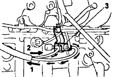
1 - to the exhaust gas recirculation system pressure modulator, 2 - from the exhaust gas recirculation system valve, 3 - electro-pneumatic valve.
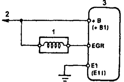
Valve connection diagram. 1 - electro-pneumatic valve, 2 - to the main relay of the fuel injection system, 3 - electronic control unit of the engine and automatic transmission.
1. Remove the valve.
2. Using an ohmmeter, make sure that there is no break in the valve winding circuit by measuring its electrical resistance.
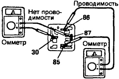
The resistance value of the valve winding at a temperature of 20°C is:
- 3S-FE, 4S-FE: 33-39 Ohm
- 5E-FE: 37-44 Ohm
Otherwise, replace the valve.
3. Using an ohmmeter, one wire of which is alternately connected to the terminals of the valve connector, and the other to the valve body, make sure that there is no short circuit between the valve winding and the body ("ground").
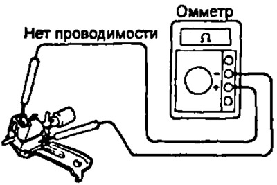
If the ohmmeter registers any resistance other than infinity, replace the valve.
3S-FE, 4S-FE
4. Check the valve operation:
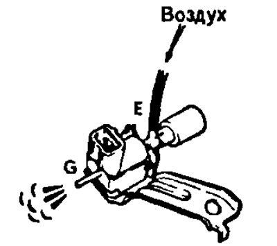
- a) Make sure that air does not pass from port "E" to port "G" through the valve.
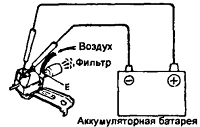
- b) Apply voltage from the battery to the terminals of the valve connector.
- c) Make sure that air flows through the valve from port "E" to the filter.
If the valve does not work properly, replace the valve.
5E-FE
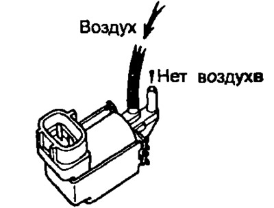
- a) Make sure that air does not pass from one hole to another through the valve.
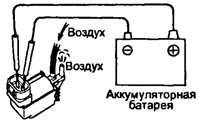
- b) Apply voltage from the battery to the terminals of the valve connector.
- c) Make sure that air passes through the valve.
If the valve does not work properly, replace the valve.
5. Reinstall the valve.