
When the engine is running and the ignition key is in the "ON" ("ON"), the magnetic field of the coil is turned off, and the core returns to its original position under the action of a return spring. Current no longer flows through the output "30", and the motor stops.
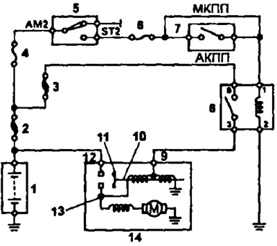
Launch system diagram (3S-FE, 4S-FE and 4A-FE) 1 - battery, 2 - main fuse '*2.0L', 3 - main fuse S40A), 4 - fusible insert "AM2" 30 A), 5 - ignition lock, 6 - fuse "ST" (7.5 A), 7 - start inhibit switch (models with automatic transmission), 8 - starter relay, 9 - starter output "50", 10 - core, 11 - contact plate, 12 - starter output "30", 13 - starter output "WITH", 14 - starter
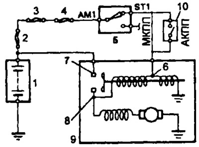
Launch system diagram (3S-GE, 5E-FE) 1 - battery, 2 - main fuse "2,0L", 3 - fusible insert "ALT" (100 A), 4 - fusible insert "AM1" (40 A), 5 - ignition lock, 6 - starter output "50", 7 - starter output "30", 8 - starter output "WITH", 9 - starter, 10 - start inhibit switch
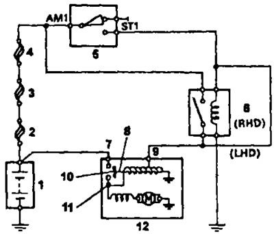
Launch system diagram (7A-FE) 1 - battery, 2 - main fuse "3,0W", 3 - fusible insert "ALT" (100 A), 4 - fusible insert "AM1" (40 A), 5 - ignition switch, 6 - starter relay, 7 - starter output "30", 8 - core, 9 - starter output "50" 10 - contact plate, 11 - starter output "WITH", 12 - starter