Anchor check
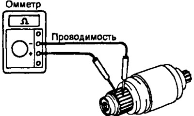
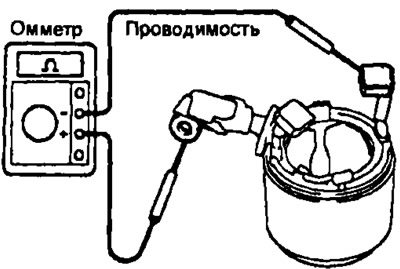
1. Using an ohmmeter, check for continuity between the collector fins. Otherwise, replace the anchor.
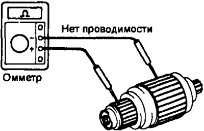
2. Check if there is a short circuit in the armature winding on "mass". Using an ohmmeter, check that there is no continuity between the collector fins and the armature core. Otherwise, replace the anchor.
Manifold check
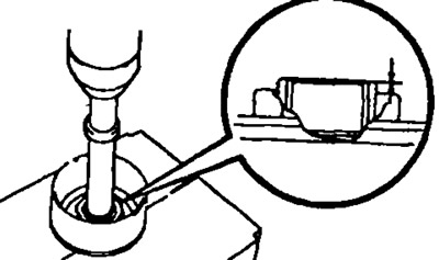
1. Inspect the working surfaces of the collector lamellas, if they are dirty and burnt, clean the working surfaces with Ne400 sandpaper or grind the collector on a lathe.
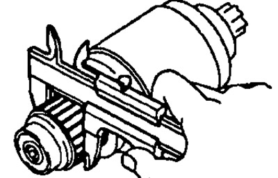
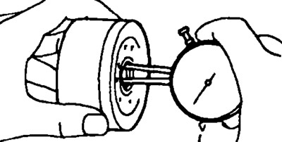
2. Mount the anchor on the prisms and measure the runout of the collector. The maximum allowable radial runout of the collector is 0.05 mm.
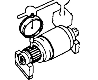
If the runout exceeds the specified value, then machine the manifold on a lathe.
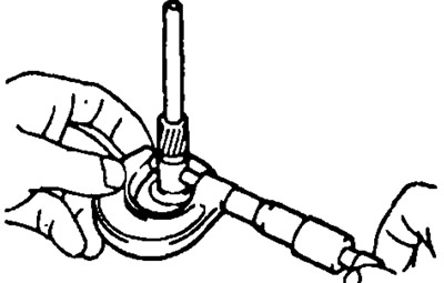
3. Using a caliper, measure the manifold diameter.
Nominal manifold diameter:
- starter 2.2 kW: 35 mm
- starters 1.0; 1.2 and 1.4 kW: 30 mm
- starter 0.8 kW: 28 mm
Minimum allowable collector diameter:
- starter 2.2 kW: 34 mm
- starters 1.0; 1.2 and 1.4 kW: 29 mm
- starter 0.8 kW: 27 mm
If the collector diameter is less than the minimum allowable, then replace the starter armature.
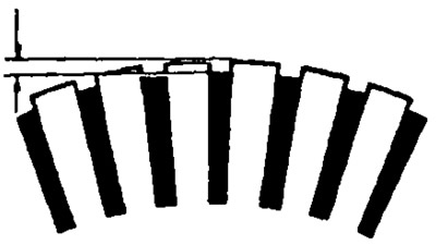
4. Check that the grooves between the collector lamellas are free of dirt and foreign particles.
Nominal protrusion of collector lamellas:
- Starters 0.8; 1.0; 1.2 and 1.4 kW: 0.6 mm
- Starters 2.2 kW: 0.7-0.9 mm
The minimum allowable protrusion of the lamellas: 0.2 mm.
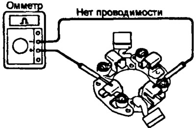
Stator check
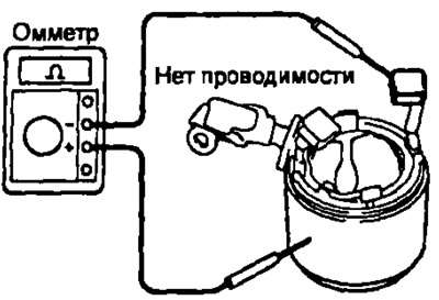
1. Using an ohmmeter, check for continuity between the wire terminal and the brush wire as shown in the figure. Otherwise, replace the starter housing assembly with the stator winding.
Except starter 2.2 kW | 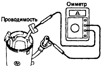
Starter 2.2 kW |
2. Check that there is no continuity between the stator winding and the housing. Otherwise, replace the starter housing complete with the stator winding.
Checking the brushes
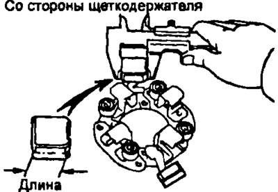
Using a caliper, measure the height of the brushes.
Nominal brush height:
- starter 0.8 kW: 14.0 mm
- starter 1.0 kW: 13.5 mm
- starters 1.2 and 2.2 kW: 15.0 mm
- starter 1.4 kW: 15.5 mm
- starter 2.2 kW (2S-T): 19.0 mm
Minimum allowable brush height:
- starter 0.8 kW: 9.0 mm
- starters 1.0 and 1.2 kW: 8.5 mm
- starter 1.4 kW: 10 mm
- starter 2.2 kW: 9.5 mm
- starter 2.2 kW (2S-T): 8.0 mm
 | 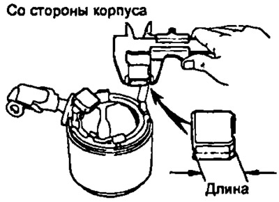 |
If the height of the brush is less than the minimum allowable value, then replace the brushes and touch up with sandpaper.
Checking brush springs
Use the steelyard to measure the tension of the brush springs at the moment of their separation from the brush.
Nominal force of brush springs:
- starter 0.8 kW 9-16 N
- starter 1.2 kW 9.8-16.7 N
- starters 1.0 and 1.4 kW: 18-24 N
- starter 2.2 kW: 26-32 N
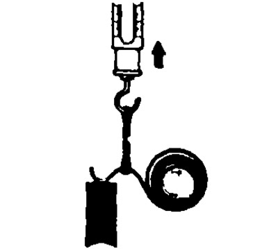
If the force of the springs is less than the minimum value, then replace the brush springs.
Check the brush holder
Check brush holder insulation. Using an ohmmeter, verify that there is no continuity between the positive "+" and negative brush holders. Otherwise, replace the brush holder.
Check freewheel and gears
1. Inspect the running surfaces of the pinion teeth, epicycle, and freewheel gear for excessive wear or chipping.
Replace gears if worn or damaged.
If there are scores or chips on the surfaces of the freewheel gear teeth, check the running surfaces of the teeth of the flywheel ring gear.
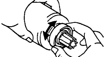
2. Check freewheel. Check that the drive gear rotates clockwise freely and counterclockwise does not rotate.
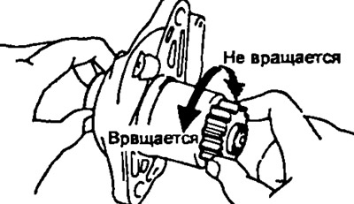
If conditions are not met, replace freewheel.
3. Replace freewheel (if necessary).
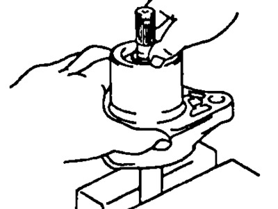
A. Drive side starter cover and freewheel disassembly.
- A) Clamp the copper rod in a vise and install the drive side starter cover with freewheel assembly onto it.
- b) Click on the drive gear.
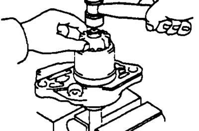
- V) Using a spool with a plastic head, upset the stop sleeve.
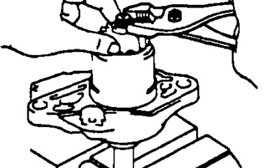
- G) Use a screwdriver to pry out the retaining ring.
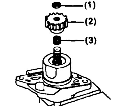
- d) Remove:
- (1) limit bushing,
- (2) drive gear,
- (3) spring.
- e) Press the starter cover on the drive side and remove the spring retainer.
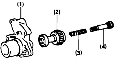
- and) Disconnect:
- (1) drive side starter cover
- (2) overrunning clutch,
- (3) spring,
- (4) clutch shaft.
B. Assemble drive side starter cover and overrunning clutch.
- A) Connect:
- (1) drive side starter cover
- (2) overrunning clutch,
- (3) spring,
- (4) clutch shaft.
- b) Clamp the copper rod in a vise and install the drive side starter cover and freewheel assembly onto it.
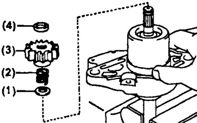
- V) Press the starter cover on the drive side and install:
- (1) spring holder,
- (2) spring,
- (3) drive gear,
- (4) restrictive bushing.
- G) Click on the drive gear.
- d) Install a new retaining ring.
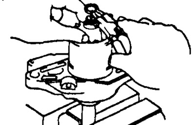
- V) Using pliers, crimp the retaining ring.
- and) Remove the freewheel drive end starter cover assembly from the copper rod.
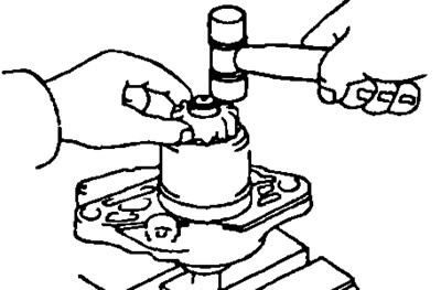
- h) Using a plastic-faced hammer, seat the freewheel shaft in place and install the stopper sleeve onto the retaining ring.
Bearing check
1. Check the front bearing. Rotate each bearing by hand while applying an axial force towards the center of the armature.
If excessive resistance is felt when the bearing rotates, or if the bearing seizes, replace the bearing.
2. Replacing the front bearing (if necessary).
- A) Remove the bearing using a puller.
- b) Using a press and a drift, press in the new front bearing.
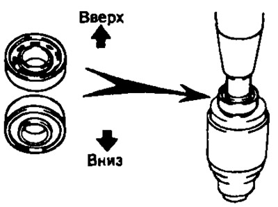
3. Check the rear bearing. Rotate each bearing by hand while applying axial force towards the center of the armature.
If excessive resistance is felt when the bearing rotates, or if the bearing seizes, replace the bearing.
4. Replace rear bearing if necessary.
- A) Remove the bearing using a puller.
- b) Using a press, press in the new rear bearing.
Checking the traction relay
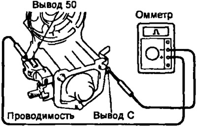
1. Checking the retracting winding of the traction relay.
Use an ohmmeter to check for continuity between the starter leads "50" And "WITH". Otherwise replace the traction relay.
Except starter 2.2 kW | 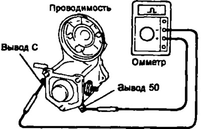
Starter 2.2 kW |
2. Checking the holding winding.
Using an ohmmeter, check that there is no continuity between the starter terminal "50" and hull. Otherwise replace the traction relay.
Check carrier and bearings (planetary gear starter)
1. Check carrier and bearings.
- A) Using a micrometer, measure the outside diameter of the bearing carrier seat. Nominal diameter: 14.035-15.000 mm.
- 6) Measure the inside diameter of the bearing. Nominal bearing inner diameter: 15.000-15.035 mm.
- V) Calculate the clearance between the bearing and carrier by subtracting the diameter of the carrier shaft from the inside diameter of the bearing. Gap:
- nominal: 0.03mm
- maximum: 0.1mm
If the clearance exceeds the maximum value, replace the carrier and bearing.
2. If necessary, replace the bearing.
- A) Remove the bearing using a puller.
- b) Using a press and a drift, press in the new bearing as shown.