
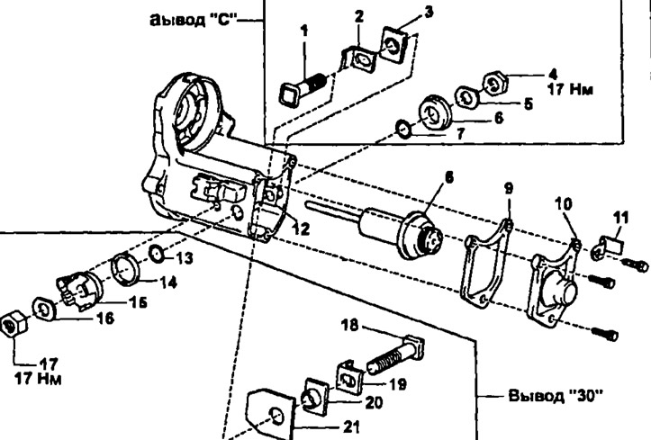
Details for disassembly and assembly of the traction relay: 1 - bolt, 2 - terminal plate, 3 - terminal insulator, 4 - nut, 5 - wave washer, 6 - terminal insulator, 7 - O-ring, 8 - plunger, 9 - gasket, 10 - cover, 11 - wiring clamp, 12 - terminal, 13 - o-ring, 14 - seal, 15 - lead insulator, 16 - wave washer, 17 - nut, 18 - bolt, 19 - contact plate, 20 - lead insulator, 21 - insulating gasket
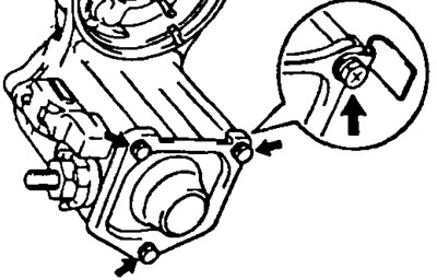
1. Loosen the three bolts and remove the wiring clamp, rear cover, gasket, and plunger.
2. Check the amount of wear on the contact plate. Use a caliper to measure the wear on the insert.
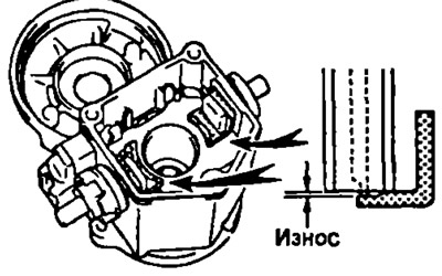
Maximum allowable wear: 0.9 mm.
If the wear exceeds the maximum allowable, replace the plate.
3. Disassembly of conclusions.
- A) Loosen the terminal nuts.
- b) Parsing output "WITH": Remove the nut, wave washer, outer terminal insulator, O-ring, bolt, contact plate, inner terminal insulator and insulating spacer.
- V) Parsing output "30": Remove the nut, wave washer, outer terminal insulator, seal, O-ring, bolt, contact plate, inner terminal insulator and insulating spacer.
4. Assembly of conclusions.
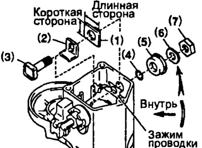
(Conclusion "30")
Install the following items as shown in the figure:
- (1) insulating pad,
- (2) internal lead insulator,
- (3) contact plate,
- (4) bolt,
- (5) ring seal,
- (6) seal and outer insulator (align the lug of the insulator with the groove of the housing),
- (7) wave washer, nut.
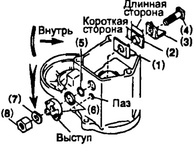
(Conclusion "WITH")
Install the following items:
- (1) internal lead insulator,
- (2) contact plate,
- (3) bolt,
- 4) ring seal,
- 5) external insulator,
- 6) wavy puck,
- (7) screw.
Temporarily tighten the terminal nuts.
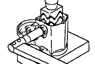
5. Tighten the terminal nuts.
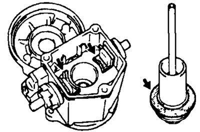
- A) Install a wooden block on the contact plate and press it in.
- Bar dimensions 20x37x40 mm
- Pressing force 981 N
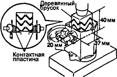
- b) Tighten nuts. Tightening torque: 17 Nm.
Note: Exceeding the torque may cause cracks on the inner surface of the insulator.
6. Clean the contact plate and plunger surfaces.
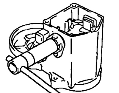
7. Install plunger, new gasket, cap, and wire clamp with three bolts.