
Examination
1. On 1999-2003 models. check that the throttle linkage operates smoothly.
2. Remove the intake air line from the throttle body and check the body for carbon deposits and other deposits. If there is dirt, clean it with an aerosol carburettor cleaner (make sure there is a special note that this product is harmless to oxygen sensors and catalytic converters) and a toothbrush (pic. 13.2).
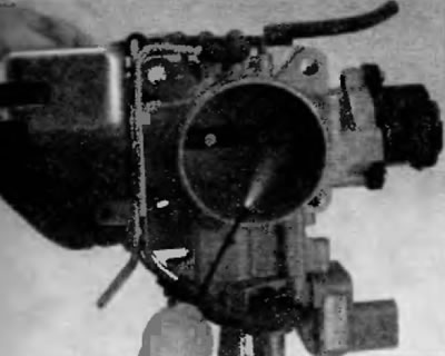
Pic. 13.2. Take an aerosol carburettor cleaner affinity, a toothbrush and a rag and with the engine off, clean the throttle body passage. Open the damper so that you can clean the area behind it
Warning. Do not use solvents to clean the throttle position sensor or idle speed control valve.
Removal and installation
Attention! Wait until the engine has completely cooled down before starting this procedure.
Models 2001-2003
3. Disconnect the ground wire from the battery (see paragraph 1 of chapter 5).
4. Remove the air inlet (see paragraph 9).
5. Disconnect the throttle position sensor electrical connector.
6. Disconnect the electrical connector for the idle speed control valve.
7. Disconnect the cruise control cable from the throttle body (pic. 13.7, a, b).
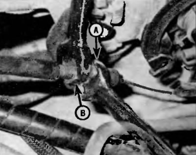
Pic. 13.7, a. To release the cruise control cable from the appropriate bracket, loosen the locknut (A) and adjustment race (IN), and then slide the cable out of the bracket (V6 model shown, similar for 4-cylinder models)
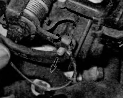
Pic. 13.7, b. To disconnect the cruise control cable from the throttle cam, align the cable with the slot on the side of the cam, and then slide the end of the cable out of the cam (showed a model with a V6 engine, for models with a four-cylinder engine similarly)
8. Disconnect the accelerator cable from the throttle body (pic. 10.2 and 10.3).
9. Disconnect the brake booster vacuum hose from the throttle body (pic. 13.9).
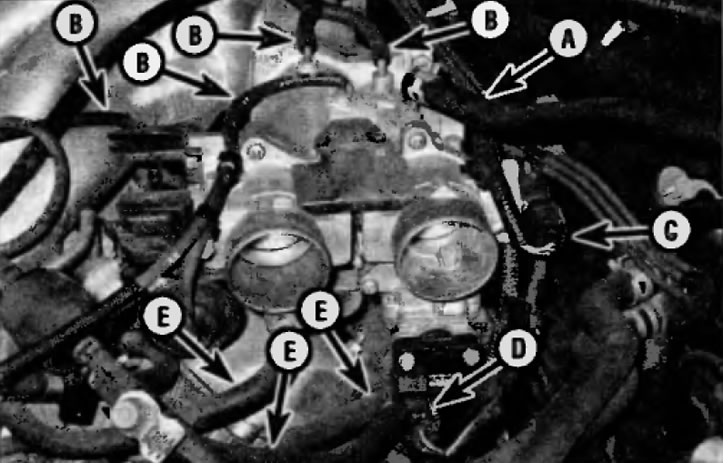
Pic. 13.9. Disconnect the brake booster vacuum hose before removing the throttle body (A) and vacuum hoses (IN), disconnect the throttle position sensor electrical connectors (TR) (WITH) and valve for controlling the frequency and rotation of the engine in idle mode (ISO) (IN), and also disconnect the coolant hoses (E)
10. Disconnect the vacuum hoses from the throttle body.
11. Pinch the coolant hoses to the throttle body to minimize fluid leakage. Plug hoses to prevent fluid from escaping.
12. Disconnect the coolant hoses from the throttle body.
13. Turn out bolts of fastening of the throttle body (four-cylinder models) or nuts (V6 models) (pic. 13.3) and remove the case.

Pic. 13.13. To disconnect the throttle body from the intake manifold by unscrewing the three nuts (V6 model shown, same for 4-cylinder models)
14. Remove gasket from throttle body and discard (pic. 13.14).
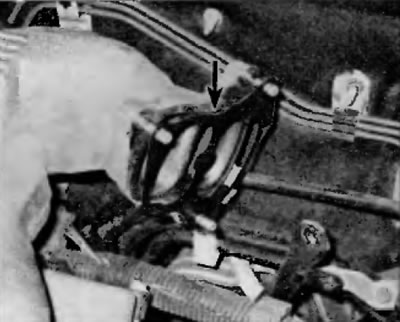
Pic. 13.14. Remove gasket from throttle body and discard (V6 model shown)
15. Installation is performed in the reverse order of removal. Tighten the throttle body mounting nuts to the specified torque as specified in Specifications at the beginning of this chapter. Check coolant level, top up if necessary (see chapter 1).
2004 and later models
16. Disconnect the ground wire from the battery (see paragraph 1 of chapter 5).
17. Remove the suspension strut brace (see chapter 10).
18. Remove the engine cover (see «Intake manifold - removal and installation» in chapter 2A or 2B).
19. Remove the intake air duct (see paragraph 9).
20. Pinch the coolant hoses to the throttle body to minimize fluid leakage.
21. Disconnect the electrical connector on the throttle body and release the wiring harness from the clip on the fuel line bracket (pic. 13.21).
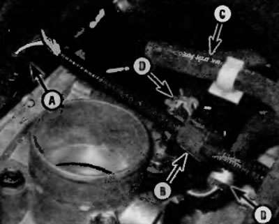
Pic. 13.21. Disconnect the electrical connector (A), release the wiring harness from the clamp (IN), release the fuel hose (WITH) from the clamp on the bracket and disconnect the coolant hoses (D) (4-cylinder model shown, similar for V6 models)
22. Release the fuel hose from the fuel line bracket, then attach identification tags to the hoses and disconnect the vacuum and coolant hoses from the throttle body (pic. 13.21). Plug hoses to prevent fluid from escaping.
23. Turn out bolts of fastening of the throttle body (pic. 13.23) and remove the case.
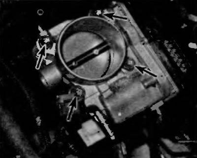
Pic. 13.23. To disconnect the throttle body from the exhaust manifold, remove the bolts (4-cylinder model shown, similar for V6 models)
24. Remove gasket from throttle body and discard.
25. Installation is carried out in the reverse order of removal. Use a new gasket and tighten the throttle body mounting bolts to the specified torque specified in Specifications at the beginning of this chapter. Check coolant level, top up if necessary (see chapter 1).