
Attention! Gasoline is highly flammable. Therefore, additional precautions must be taken when working on the fuel system. See warning in paragraph 2.
1. Relieve fuel pressure (see paragraph 2).
2. Disconnect the ground wire from the battery (see paragraph 1 of chapter 5).
3. Remove the engine cover (see «Intake manifold - removal and installation» in chapter 2A or 2B).
4. Remove the air inlet (see paragraph 9).
Models with a four-cylinder engine
5. Disconnect the electrical connectors at the fuel injectors and set the injector wiring harness aside.
6. Disconnect the fuel supply line from the fuel pressure pulsation damper (see paragraph 4).
7. Turn out bolts of fastening of a fuel stage (pic. 15.7).
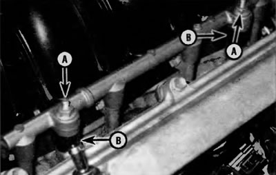
Pic. 15.7. To disconnect the fuel rail from the intake manifold on models with a four-cylinder engine, screw in the bolts (A). After removing the fuel rail and injectors, remove and check the condition of the remote elements (IN). If they are damaged, replace them
8. Remove the fuel rail and fuel injectors as a single assembly.
9. To remove the fuel injectors and replace the O-rings in them, refer to p.p. 23 and 24.
10. Installation is carried out in the reverse order of removal. Tighten the fuel rail mounting bolts to the specified torque specified in Specifications at the beginning of this chapter.
Models with V6 engine
Application. On these models, the fuel rail actually consists of two sections. The front fuel rail houses the fuel injectors for the front row cylinders. The rear fuel rail houses the injectors for the rear row cylinders. In case of leakage only through the o-ring/seal of one injector, it is still recommended to replace the o-rings of all injectors. Most fuel rails require the entire assembly to be removed. Therefore, to avoid having to remove the fuel rail later to replace another o-ring and/or seal, all o-rings/seals should be replaced at the same time. However, if the leak occurs in only one front bank injector, note that you have the option of removing the front fuel rail without removing the rear fuel rail. This means you don't have to remove the intake manifold. Conversely, it is possible to remove the rear fuel rail without removing the front fuel rail, although you will need to remove the intake manifold to do so. Finally, in the event of a single injector leaking, it is recommended that all injectors be removed and all o-rings and/or seals replaced. Removing the intake manifold on these cars is not very difficult.
11. Remove the suspension strut brace (see paragraph 3 of chapter 10).
12. Remove the intake manifold (see chapter 2B).
13. Disconnect the electrical connectors of the injectors on the front cylinder head (pic. 15.13).
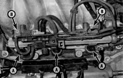
Pic. 15.13. Disconnect electrical connectors (A) fuel injectors on the front cylinder head. To detach the vacuum changeover valve support bracket (VSV) from the intake manifold, unscrew the two nuts (IN) (V6 models)
14. Remove the vacuum changeover valve support bracket (VSV) from intake manifold (pic. 15.13) and set the bracket aside. Do not disconnect vacuum hoses.
15. If you are going to remove the entire fuel rail assembly, disconnect the fuel feed line from the fuel rail (see paragraph 4).
16. If you are only going to remove the front fuel rail, disconnect the metal cross pipe that connects the front fuel rail to the rear. To do this, unscrew the bolt of the fitting type «banjo» (hollow) from the front fuel rail (rice. 3.8). If you are going to remove the rear fuel rail, remove the pressure pulsation damper from this rail (rice. 14.8) and remove the cross pipe. Remove sealing washers and discard (when assembling, use new).
17. If you are removing only the front fuel rail and injectors, remove the front fuel rail mounting bolts (pic. 15.21) and remove this rail and injectors by pulling the assembly straight up.
18. To remove the fuel injectors and replace their o-rings, refer to p.p. 23 and 24 below.
19. If you are going to remove the entire fuel rail assembly (or just the rear fuel rail), remove the intake manifold (see chapter 2B).
20. Disconnect the electrical connectors on the rear fuel rail (fig 15.20).
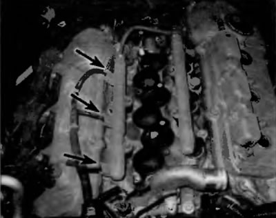
Pic. 15.20. Disconnect the electrical connectors for the rear fuel injectors (V6 models)
21. Turn out bolts of fastening of a fuel stage (pic. 15.21).
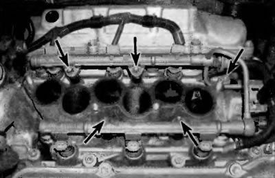
Pic. 15.21. To disconnect the fuel rail assembly from the intake manifold, remove these bolts (V6 models)
22. Remove the fuel rail and fuel injectors as a single unit (pic. 15.22).
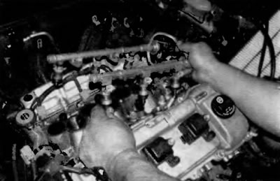
Pic. 15.22. Remove the fuel rail and injectors as a single unit
23. Remove the fuel injectors from the fuel rail (pic. 15.23).
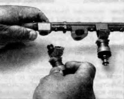
Pic. 15.23. To remove each injector from the fuel rail, pull it out of the rail while unscrewing
24. If you intend to continue using the same nozzles, replace the grommets and o-rings (pic. 15.24).
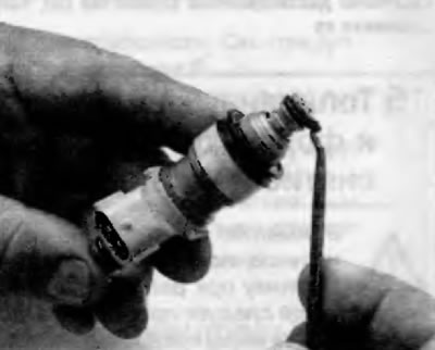
Pic. 15.24. If you plan to return to the place «junk» injectors, remove the O-rings and sealing bushes from them and replace them with new ones
25. Installation is carried out in the reverse order of removal. Use new injector O-rings and tighten the fuel rail mounting bolts to the specified torque specified in Specifications at the beginning of this chapter.