
Attention! Wait until the engine has completely cooled down before starting this procedure.
Removing
1. Depressurize the fuel system (see chapter 4), then disconnect the ground wire from the battery (see paragraph 1 of chapter 5).
2. Remove the cover (And) engine (rice. 4.2, a, b).
Upper intake manifold
Note. The next procedure is to remove the upper intake manifold to access the rear cylinder head cover, rear cylinder head and sensors. However, for spark plug removal, compression checks, and fuel rail service, the upper intake manifold can be separated from the throttle body, leaving the air filter housing and throttle body in place.
3. On 2004 and later Highlander models and all Lexus models, remove the bonnet top panel/air box deflector (see chapter 11).
4. On 2004 Highlander models. and later and all Lexus models, remove the windshield wiper arms and windshield wiper motor (see chapter 12).
5. On Highlander 2004 and later and all Lexus models, remove the lower hood panel (see chapter 11).
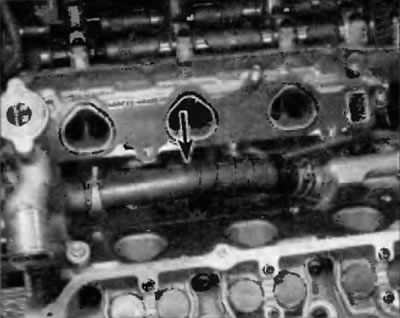
6. Disconnect the positive crankcase ventilation hose from the cylinder head cover (pic. 5.6).
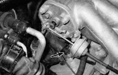
Pic. 5.6. Location of the forced crankcase ventilation hose on the rear cylinder head cover
To remove spark plugs
7. Disconnect ground rail, variable geometry air intake system components (ACIS) (see chapter 6) and vacuum lines (pic. 5.7) from the upper intake manifold and disconnect the appropriate electrical connectors. Using masking tape and a marker, mark each electrical connector to ensure correct assembly.
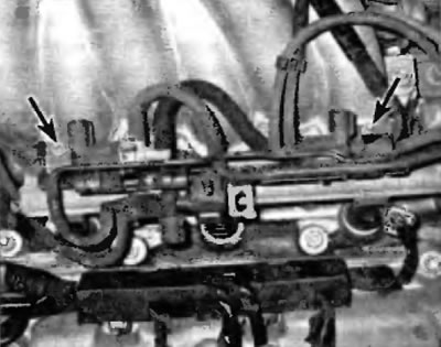
Pic. 5.7. Loosen the nuts, remove the vacuum block from the upper intake manifold and position the welding aside
8. Turn away nuts of fastening of the throttle body (pic. 5.8).
Pic. 5.8. Location of throttle body mounting nuts (2001 model shown, later models similar)
9. Turn out bolts and remove coupler (And) at the rear of the upper intake manifold.
10. Turn out bolts and turn away nuts of fastening of the top inlet manifold to the lower inlet manifold (pic. 5.10).
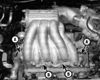
Pic. 5.10. Bolt location (IN) and nuts (A) upper intake manifold mounting (3.0L VG engine shown, similar for 3.3L V6 engine)
11. Remove the two Torx screws (A) from the cylinder head (pic. 5.10).
12. Move the upper intake manifold to the side and separate it from the throttle body and lower intake manifold (pic. 5.12).
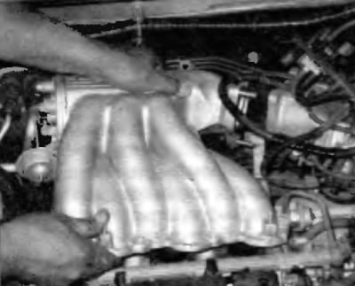
Pic. 5.12. Move the upper intake manifold to the side to disconnect it from the throttle body
For all other procedures
13. Disconnect the ground bus, elements of the air intake system with variable geometry (ACIS) (see chapter 6) vacuum lines (pic. 5.7) and coolant bypass hoses from the upper intake manifold/throttle body assembly, and disconnect the related electrical connectors. Note. Before disconnecting the coolant hoses, pinch them or plug the hoses immediately after disconnecting. Be prepared for coolant to leak out. The throttle body can be left connected to the upper intake manifold unless it needs to be removed for gasket maintenance or cleaning. Using masking tape and a marker, mark each electrical connector to ensure correct assembly.
14. Remove the air filter housing and intake ducts (see chapter 4).
15. Disconnect the accelerator cable (see chapter 4) or disconnect the electronic throttle control electrical connector (see chapter 6) on the throttle body.
16. Remove the tie between the two suspension struts (see paragraph 3 of chapter 10).
17. Turn out bolts and remove coupler (And) upper intake manifold and throttle body tie at the rear of the upper intake manifold.
18. Remove the bolts and nuts securing the upper intake manifold to the lower intake manifold and remove the upper intake manifold assembly with the throttle body from the engine compartment (pic. 5.10).
Lower intake manifold
19. Drain the coolant into a clean container (see chapter 1).
20. Disconnect the electrical connectors on the fuel injectors (see chapter 4). Also disconnect the fuel line from the fuel rail (see chapter 4).
Note. The intake manifold can be removed with or without the injectors and fuel rail, depending on the nature of the work to be done.
21. Disconnect the heater hoses from the lower intake manifold.
22. Remove the bolts and remove the two nuts, working in the reverse order of tightening, then disconnect the lower intake manifold from the engine (pic. 5.26). If the manifold does not come off, do not pry it by inserting any lever between the mating surfaces, as this may damage the joint.
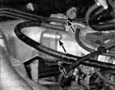
23. After removing the intake manifold, access to the coolant connecting hose is opened (pic. 5.23). Due to the difficulty of accessing this hose to replace it, it is recommended to replace it with a new one each time the intake manifold is removed for any other work.
Pic. 5.23. This coolant hose should be replaced every time the intake manifold is removed for any other repair
Installation
24. Scrap all traces of old gasket material and sealant from lower intake manifold and cylinder heads, then clean mating surfaces with lacquer thinner or acetone.
25. Install new gaskets, then install the manifold on the engine. Take care not to move the gaskets, then loosen the nuts/bolts.
26. Tighten the nuts/bolts evenly in three or four stages to the prescribed torque shown in Specifications at the beginning of this chapter. Tighten the bolts in the correct sequence (pic. 5.26).
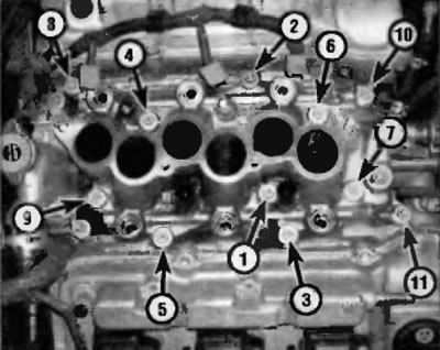
Pic. 5.26. Lower intake manifold tightening sequence
27. Establish remaining elements, working in sequence, return to removal. Install a new gasket between the lower intake manifold and the upper intake manifold (pic. 5.27).
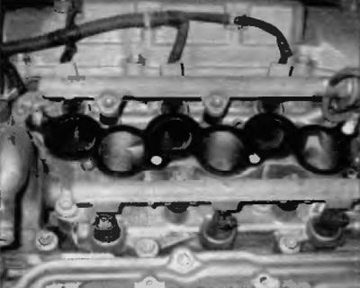
Pic. 5.27. Install a new gasket after the surface of the lower intake manifold has been properly prepared
28. Prime the cooling system. Start the engine and check for fuel, vacuum, and coolant leaks.