
Attention! Gasoline is highly flammable. Therefore, when working with any take extra precautions. See warning in paragraph 2.
Application. Once the fuel pump/fuel gauge sensor assembly has been removed from the fuel tank, the entire assembly can be replaced, or the assembly can be disassembled and replaced with an intake strainer, fuel pressure regulator, calibrated return, fuel pump, fuel filter, or fuel gauge sensor. The disassembly order shown here is for a typical fuel pump used on the 1999-2003 medals. The pump used on 2004 and later models is slightly different.
1. Remove the fuel pump in the block with the fuel gauge sensor from the fuel tank (see paragraph 5).
2. Drain any remaining gasoline from the fuel pump at the gauge box, and then place the assembly on a clean workbench. Make sure that the working area is well ventilated, because gasoline will evaporate from the fuel pump for some time.
3. Gently pry off the end cap on the lower end of the fuel pump in the sensor assembly (pic. 6.3).
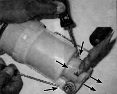
Pic. 6.3. To remove the bottom end cap, carefully use a pair of screwdrivers to loosen each of the locking tabs and then remove the end cap
4. Remove the rubber support from the lower end of the fuel pump (pic. 6.4).
Pic. 6.4. Remove the small rubber mount shown from the lower end of the fuel pump and inspect it. If it is damaged, replace
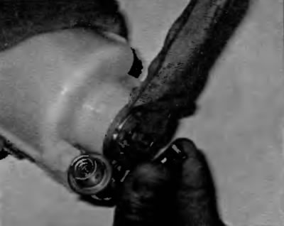
5. Remove the strainer at the fuel pump inlet (pic. 6.5) from the bottom end of the fuel pump.
Pic. 6.5. The intake strainer is secured to the lower end of the fuel pump with an E-clip. To detach the strainer from the pump, insert a screwdriver between the strainer support flange and the pump, gently pry the strainer and E-clip to release them (do not try to pry directly on the clamp - it is too difficult to insert a screwdriver under it)
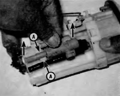
6. Remove the fuel pressure regulator (pic. 6.6).
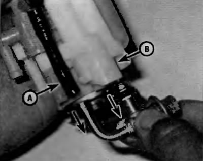
Pic. 6.6. Disconnect the fuel pressure regulator from the calibrated return hose (A) and from the fuel filter (IN)
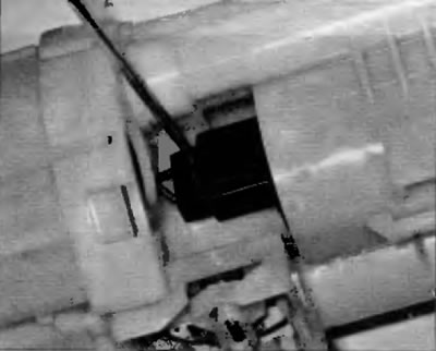
7. Remove the calibrated return tube assembly (pic. 6.7).
Pic. 6.7. To disconnect the calibrated return assembly, simply pull it out of the clamp (A)
8. Remove the fuel pump from the fuel filter assembly (pic. 6.8, a, b).
Pic. 6.8, a. To disconnect the fuel pump electrical connector, press the locking tab and pull out the plug
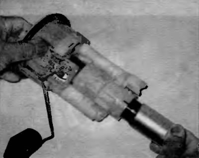
Pic. 6.8b. To remove the fuel pump from the fuel filter housing, pull it away from the bottom of the
9. Separate the fuel filter housing from the top section of the fuel pump assembly (pic. 6.9). If you are replacing the fuel filter, you must replace this housing. The fuel filter is not supplied separately from the housing.
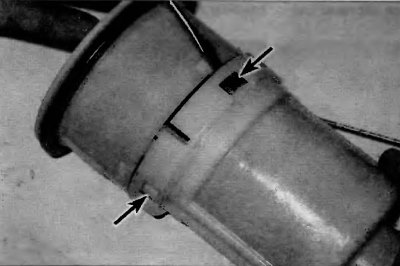
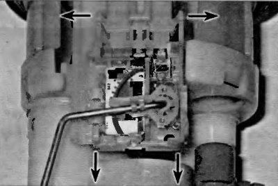
Pic. 6.9. To separate the fuel filter housing from the top section of the pump assembly, carefully release the four retaining tabs from the filter housing and pull both elements in opposite directions
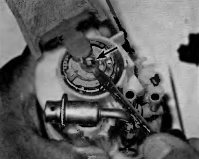
10. Disconnect the fuel gauge sensor from the top section of the fuel pump assembly (pic. 6.10).
Pic. 6.10. To disconnect the fuel level sensor from the top section of the fuel pump assembly, release both retaining elements from the tabs on the top section of the pump, then slide the sensor straight down. When installing the sensor, slide it into its regular place until the two fixing elements snap into place in the projections
11. Assembly is carried out in the reverse order of disassembly.
12. Install the fuel pump in the block with the fuel gauge sensor in the fuel tank (see paragraph 5).