



Contents: Checking the fuel gauge ↓ Checking the resistance of the fuel…↓ Checking the operation of the fuel…↓ Checking the resistance of the sensor ↓ Checking the fuel reserve indicator ↓ Checking the fuel reserve sensor ↓ Fuel filter water presence sensor ↓ Fuel heater ↓
Checking the fuel gauge
1. Disconnect the connector from the fuel level sensor.
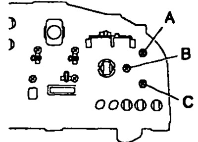
2. Turn on the ignition and check that the fuel gauge pointer points to the "EMPTY" mark.
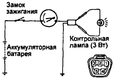
3. Connect a 3W test lamp between terminals "2" and "3" (models since 1996 - terminals "3" and "4") of the connector on the wire side.
4. Turn on the ignition, check that the indicator light illuminates and the fuel gauge pointer deflects to "FULL".
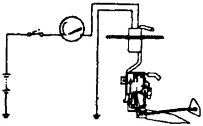
Note: Because the fuel gauge is filled with silicone oil, the gauge needle moves slowly.
If the sensor operation is different from the description, replace the sensor.
Checking the resistance of the fuel level indicator
Measure the resistance between the terminals:
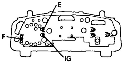
Models before 1996 with tachometer
Resistance between terminals:
- F—E ~ 131 Ohm
- F—IG ~ 123 Ohm
- IG — E ~ 304 Ohm
Models after 1996.
Resistance between terminals:
- A - B ~ 252 Ohm
- A - C ~ 355 Ohm
- B - C ~ 103 Ohm
If the resistance differs from the specified value, replace the indicator.
Checking the operation of the fuel level sensor
1. Disconnect the connector from the fuel level sensor.
2. Connect the "+" of the 4.5V DC power supply (for example, 3 batteries) to terminal "2" via a 3.4 W test lamp, connect the "-" of the source to terminal "3".
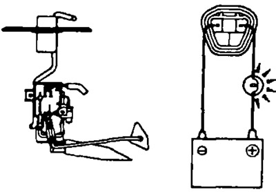
3. Check that the voltage between pins "2" and "3" appears lamp illuminates) when the gauge float drops from the upper to lower position.
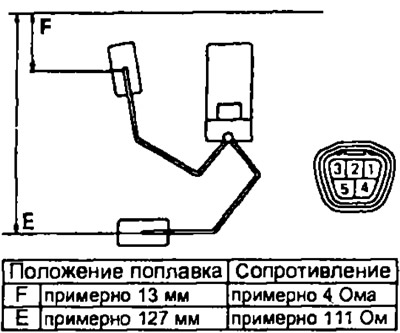
Checking the resistance of the sensor
Models before 1996
Measure the resistance between terminals "2" and "3" for each float position.
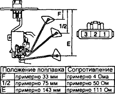
Models after 1996
Measure the resistance between terminals "2" and "3" for each float position.
Checking the fuel reserve indicator
1. Disconnect the connector from the fuel level sensor.
2. Short-circuit terminals "1" and "3" of the connector on the wire side.
3. Turn on the ignition, check that the fuel reserve indicator lights up. Otherwise, check the lamp.
Checking the fuel reserve sensor
1. Connect the battery to terminals "1" and "3" via a 3.4 W test lamp. Check that the test lamp lights up.
Note: The indicator lamp will light after a short period of time.

2. Immerse the sensor in fuel. Check that the indicator lamp goes out.
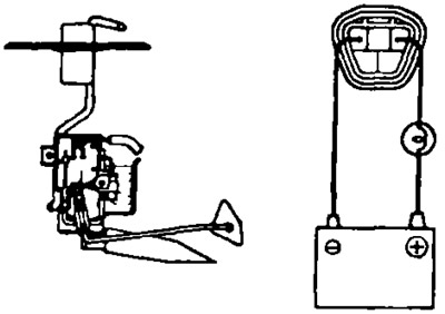
If operation is not as described, replace the sensor.
Fuel filter water presence sensor
1. Check for conductivity between the sensor terminals when the float is in the upper position.
2. Check for conductivity between the sensor terminals when the float is in the lower position. If it does not work properly, replace the sensor.
Fuel heater
1. Create a vacuum (about 47 kPa) in the vacuum sensor.
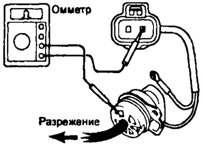
2. Check for conductivity between terminal "1" and the switch body.