
Removing
Apply the parking brake and chock the rear wheels.
Loosen the front wheel nuts. Raise the front of the car and place it on stands. Remove the front wheel.
On models prior to 2001, remove the nut and disconnect the anti-roll bar link from the lower front suspension arm.

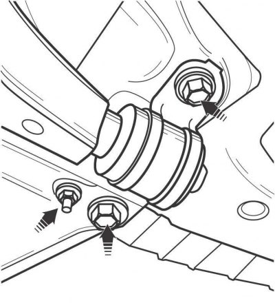
Pic. 12.11. Arrangement of a bolt and nuts of fastening of the spherical hinge to the lower arm of a forward suspension bracket
Remove the bolt and two nuts securing the ball joint to the lower arm of the front suspension (pic. 12.11). Use a pry bar to separate the ball joint from the lower arm of the front suspension
Turn out the hinge bolt of fastening of the front side of the lower arm. On pre-2001 models with automatic transmission, when removing the left arm, remove the bolts, lower the lower cross member and remove the lower arm front side hinge bolt.
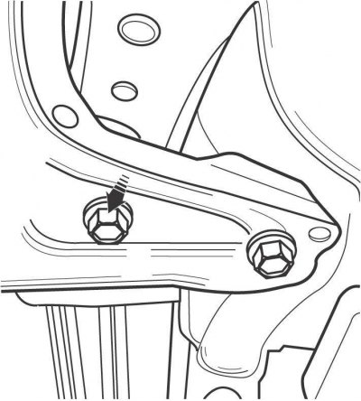
Pic. 12.12. Arrangement of bolts and nuts of fastening of an arm with the basic plug of the back party of the bottom lever on models till 2001
On models up to 2001, unscrew the two bolts and nut and remove the bracket with the support sleeve for attaching the rear side of the lower arm (pic. 12.12).
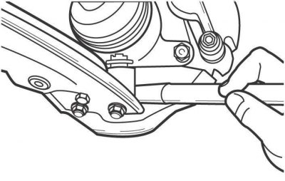
Pic. 12.13. The location of the support sleeve bolt of the rear side of the lower arm on models from 2001
On models since 2001, remove the bolt securing the support sleeve on the rear side of the lower arm (pic. 12.13).
Remove the lower arm.
Inspect the lever for deformation, signs of corrosion and wear of the support bushings. It is forbidden to straighten a deformed lever.
Installation
Install in the reverse order of removal.
Check and, if necessary, adjust the angles of the front wheels.
Replacing the ball joint of the lower arm of the front suspension
Apply the parking brake and chock the rear wheels.
Loosen the front wheel nuts. Raise the front of the car and place it on stands. Remove the front wheel.
Remove the cotter pin from the ball joint trunnion and loosen the nut securing the ball joint to the steering knuckle.
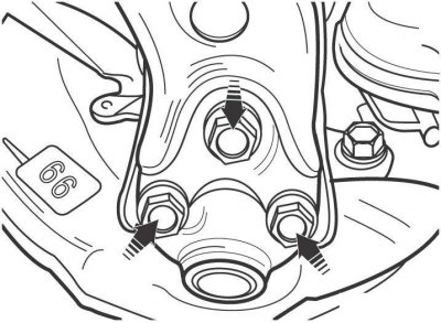
Pic. 12.14. Using a puller to separate the ball joint trunnion from the steering knuckle
Using a pry bar or puller, separate the ball joint pin from the steering knuckle (pic. 12.14). Loosen, as far as possible, the nut securing the ball joint trunnion. The gap between the pin of the ball joint and the CV joint of the wheel drive shaft is small and does not allow you to unscrew the nut in one go. Therefore, proceed as follows: unscrew the nut by 1-2 turns and press the ball joint down, unscrew the nut again by 1-2 turns and press the ball joint down, and so on until the nut is completely unscrewed.
Pic. 12.11. Arrangement of a bolt and nuts of fastening of the spherical hinge to the lower arm of a forward suspension bracket
Remove the bolt and two nuts securing the ball joint to the lower arm of the front suspension (see fig. 12.11). Use a pry bar to separate the ball joint from the lower front suspension arm and remove from the vehicle.
Insert the ball joint trunnion into the steering knuckle hole and screw the nut onto the trunnion.
Install the lower arm onto the ball joint and secure it with the bolt and nuts, tightening them to the torque specified in the technical data.
Tighten the nut securing the ball joint pin to the steering knuckle and install a new cotter pin. If the hole in the cotter pin does not line up with the slots on the nut, turn the nut in the tightening direction until the slots on the nut line up with the hole.
Further installation is carried out in the reverse order of removal.