



On 2001 and later models, disconnect the stabilizer bar link from the lower control arm.
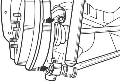
Figure 12.21. Location of the nuts securing the upper and lower wishbones to the rear steering knuckle on models before 2001
On pre-2001 models, remove the cotter pin, loosen the nut, and separate the lower control arm ball joint pin from the rear steering knuckle (figure 12.21). If the ball joint pin does not separate by hand, remove it using a puller.
On pre-2001 models, remove the nut and bolt securing the lower control arm to the bracket on the rear trailing arm.
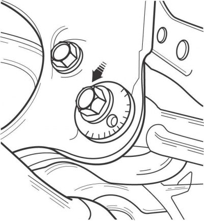
Figure 12.23. Location of the adjusting cam for the inner mount of the lower wishbone of the rear suspension
Use paint or a marker to mark the position of the adjusting cam so that you can later return the lever to its original position and maintain the rear wheel alignment angles (figure 12.23).
Loosen the nut and remove the pivot bolt of the inner mount of the lower arm.
Remove the lower control arm from the vehicle.
Check the condition of the lever. There should be no cracks or deformations on it. The bushing must not have any wear, delamination or hardening of the rubber.
On pre-2001 models, check the condition of the lower control arm ball joint by clamping the control arm in a vice. Tilt the ball joint pin as far as it will go in one direction and then screw the nut onto the pin. Using a torque wrench, rotate the ball joint pin (one revolution every 2–4 seconds), and at the fifth revolution, measure the turning torque, which should be at least 0.7 N·m. Otherwise, replace the upper control arm.
Installation is carried out in the reverse order of removal.
Check and adjust rear wheel alignment angles if necessary.