
Removing
1. Remove the oil pan (see paragraph 12).
2. Remove the timing belt (see paragraph 7).
3. Remove the crankshaft sprocket (see paragraph 7) and crankshaft position sensor (see chapter). Place a jack under the engine. Remove power unit mounts (see paragraph 16).
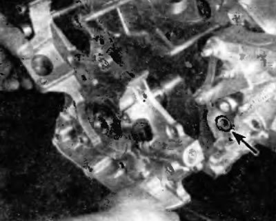
4. Remove the oil pickup (pic. 13.4)
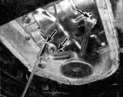
Pic. 13.4. The oil inlet pipe is fixed with three fasteners
5. Remove the generator and its bracket (see chapter 5).
6. Turn out bolts and remove the conditioner compressor. Position it towards the refrigerant line disconnect bases.
7. Remove A/C compressor bracket (pic. 13.7).
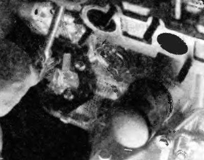
Rns. 13.7. Turn out bolts and remove an arm of the compressor of the conditioner from the block of cylinders
8. Remove the power steering pump adjusting bracket, pry the pump and separate it from the oil pump housing (pic. 13.8)
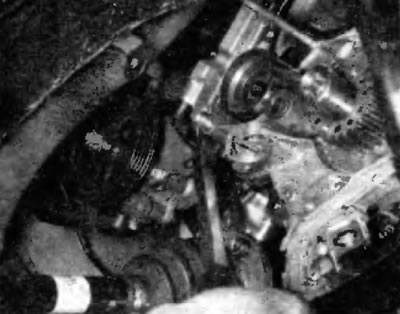
Pic. 13.8. Remove the power steering pump adjusting bar, pry and separate the pump from the oil pump housing
9. Remove the timing belt tensioner pulley (pic. 13.9).
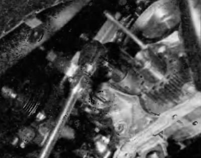
Pic. 13.9. Using a hex bit or 18mm hex socket wrench, remove the belt tensioner pulley
10. Turn out bolts and disconnect the oil pump from the engine. It may be necessary to gently pry with a screwdriver and separate the front main bearing cap and pump housing.
11. Remove the o-ring. Remove the circlip, retainer, spring and oil safety valve valve itself (pic. 13.11).
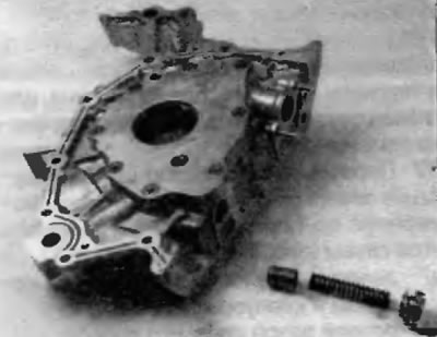
Pic. 13.11. Remove the plug, spring and oil pressure relief valve
Attention! The spring is highly compressed, so be careful and wear eye protection.
12. Using a large Phillips screwdriver, remove the screws securing the housing cover to the rear of the oil pump (pic. 13.12).
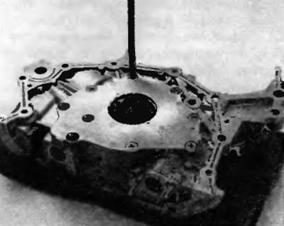
Pic. 13.12. Using a large Phillips screwdriver or appropriate bit, remove the pump cover bolts
13. Remove cover and remove pump impellers.
14. Scrap all traces of sealant and old gasket material from pump housing and cylinder block, then clean mating surfaces with lacquer thinner or acetone.
Inspection
15. Clean all elements with solvent and then inspect them for wear and damage.
16. Check the oil relief valve seat and valve spring. If the spring or valve is damaged, they must be replaced as a complete set.
17. Use a feeler gauge to check the following gaps and compare the measurements with specifications at the beginning of this chapter (pic. 13.17, a-c):
- A) gap between the driven impeller and the pump casing;
- b) axial clearance of the impeller;
- V) gap on the heads of the teeth of the impellers.
Ryas. 13.17, a. Use a feeler gauge to measure the gap between the driven impeller and the casing
Pic. 13.17, b. Measure the axial clearance of the impellers using a rigid straightedge and a set of feeler gauges
Pic. 13.17, c. Using a feeler gauge, measure the clearance on the heads of the impeller teeth. Impeller marks facing outwards (with the pump body cover installed, the marking will face the cover)
Installation
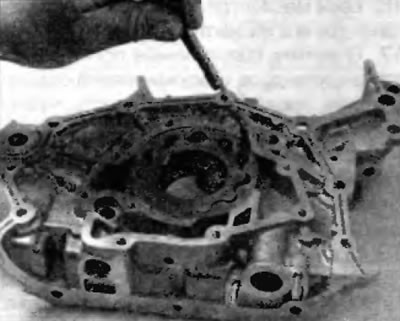
18. Using a screwdriver, remove the old crankshaft seal.
19. Apply multipurpose grease or engine oil to the outer edge of the new oil seal and carefully insert the oil seal using a suitable drift and hammer. Apply multipurpose grease to the sealing lip.
20. Install the driving and driven impellers in the pump housing with the marks facing out (pic. 13.17, in).
21. Stuff the pump cavity with petroleum jelly and install the cap. Tighten the screws securely in a criss-cross pattern.
22. Lubricate the oil relief valve with engine oil and install the valve elements in the pump housing.
23. Using acetone or lacquer thinner and a clean rag, remove all traces of oil from the sealing surfaces.
24. Apply anaerobic sealant in a 2-3 mm wide bead to the oil pump. Do not use excessive amounts of sealant, especially around oil passages and bolt holes.
25. Establish a new sealing ring on the block of cylinders.
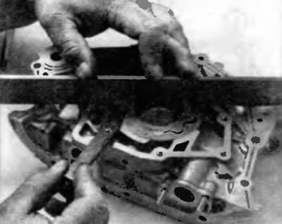
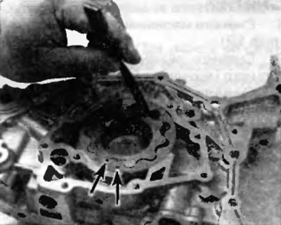
26. Align the flats on the driving impeller of the oil pump with the flats on the crankshaft and insert the pump into place (pic. 13.26).
Pic. 13.26. Install the left O-ring on the cylinder block and align the driving impeller and crankshaft when installing the oil pump
27. Screw in the oil pump mounting bolts according to their original position and tighten them in a cross sequence to the prescribed torque specified in Specifications at the beginning of this chapter.
28. Using a new gasket, install the oil suction pipe and tighten the fasteners to the prescribed torque specified in Specifications at the beginning of this chapter.
29. Reinstall the remaining elements, working in the reverse order of removal.
30. Fill with oil, start the engine and check for oil leaks.
31. Check the engine oil level again.