
Remove an overlay of a threshold of a back left door.
Remove the front trim of the seat inner rail bracket.
Remove the front trim of the outer seat rail bracket.
Remove the rear trim of the seat inner rail bracket.
Remove the rear trim of the outer seat rail bracket.
Remove the rear left seat assembly.
Removing the Rear Access Port Cover
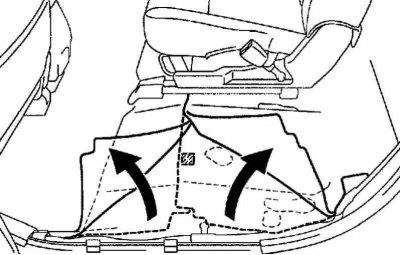
Pic. 2.499. Floor mats
Raise the front and rear floor mats (pic. 2.499).
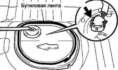
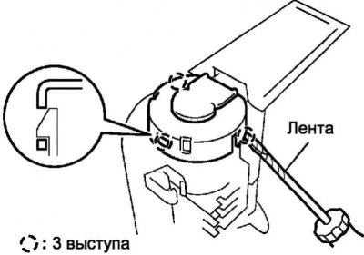
Pic. 2.500. Rear service port cover
Remove the butyl tape and remove the rear access port cover (pic. 2.500).
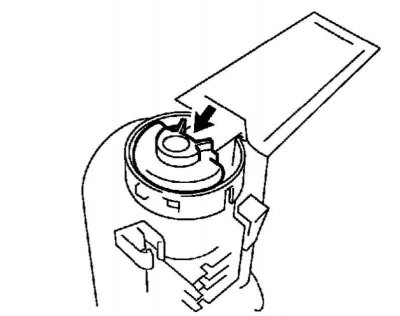
Disconnect the fuel pump connector.
Reduce the pressure in the fuel system.
Start the engine.
After stopping the engine, turn off the ignition (OFF).
Note. DTC P0171 may be output (no fuel in the system).
Turn the engine over with the starter again. Make sure the engine does not start.
Remove the fuel tank cap so that the pressure in it is equal to atmospheric pressure.
Removal of a branch pipe of a fuel inlet with the pump and the gauge of level of fuel assy
Disconnect the fuel supply line from the fuel tank.
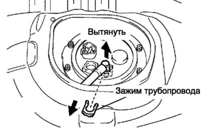
Pic. 2.501. Fuel intake pipe
Remove the clip, then pull the connecting pipe out of the fuel intake plate (pic. 2.501).
Note. Before performing work, wipe off dirt and foreign particles from the joints of the parts.
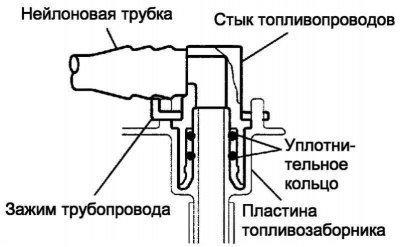
Pic. 2.502. Fuel pickup connection
Disconnect the parts carefully so that no scoring is formed and foreign particles do not get on the parts, since the nozzle has an o-ring that ensures tightness of the connection with the fuel intake plate, which can be damaged (pic. 2.502).
The work is done by hand. The use of another tool is prohibited.
Do not forcefully bend or twist the nylon tube.
After disconnecting the fuel pump pipe, the connected part should be closed with a plastic bag and adhesive tape.
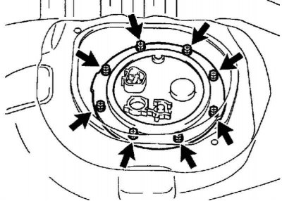
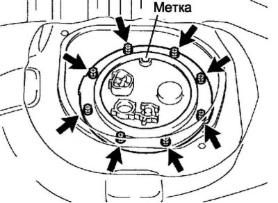
Pic. 2.503. Bolts of fastening of a plate of fastening of a ventilating tube of a fuel tank
Remove 8 bolts, then remove the fuel tank vent tube mounting plate (pic. 2.503).
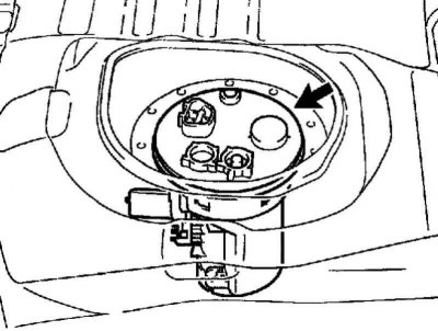
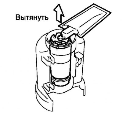
Pic. 2.504. Fuel pump assembly
Remove the fuel intake assembly with the pump and the fuel level sensor from the fuel tank (pic. 2.504).
Note. This operation must be carried out carefully so as not to damage the fuel pump filter.
Note. Be careful not to bend the sensor arm.
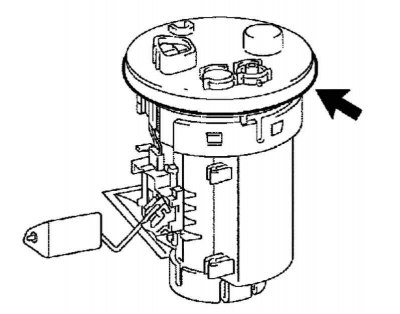
Pic. 2.505. Fuel intake gasket
Remove the gasket from the fuel intake with the pump and fuel level sensor assembly (pic. 2.505).
Removing the fuel level sensor assembly
Disconnect the fuel level sensor connector.

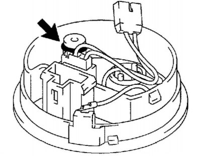
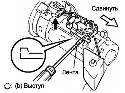
Pic. 2.506. Removing the fuel level sensor
Use a screwdriver with a tape-wrapped blade to pry out the tab on the latch. Then move the fuel level sensor and remove it from the fuel filter (pic. 2.506).
Removing the fuel intake plate assembly
Disconnect the fuel pump connector.
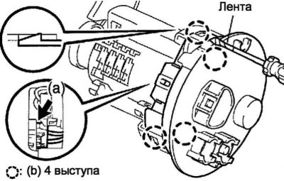
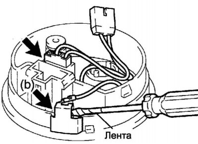
Pic. 2.507. Removing the fuel intake plate assembly
Use a screwdriver with a tape-wrapped blade to bend the 4 tabs on the tabs. Then remove the fuel pickup plate (pic. 2.507).
Note. This operation must be carried out carefully so as not to damage the fuel intake plate and the fuel filter.
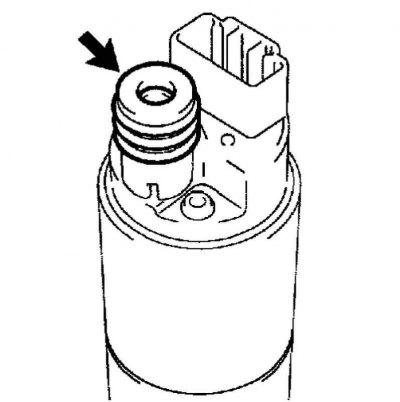
Pic. 2.508. Sealing ring
Remove the o-ring from the fuel intake plate (pic. 2.508).
Removing the fuel pump wiring harness
Disconnect the fuel pump harness connector.
Pic. 2.509. Removing the ground terminal
Using a screwdriver with a thin blade wrapped with electrical tape, remove the ground terminal (pic. 2.509).
Removing the Fuel Pressure Regulator Assembly
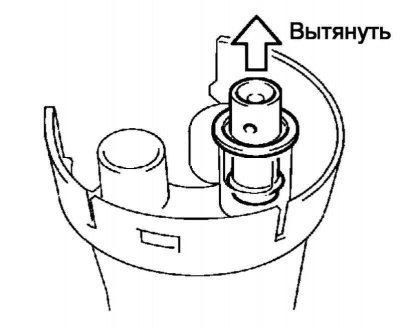
Pic. 2.510. Removing the fuel pressure regulator
Remove the fuel pressure regulator from the fuel filter (pic. 2.510).
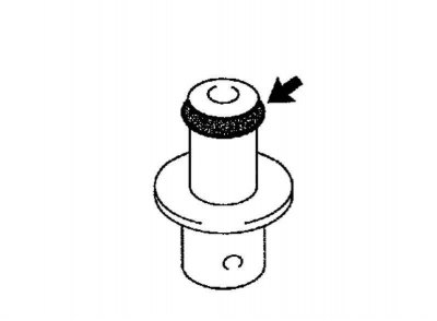
Pic. 2.511. Removing the sealing ring
Remove the o-ring from the fuel pressure regulator (pic. 2.511).
Removing the support of the fuel intake No. 2
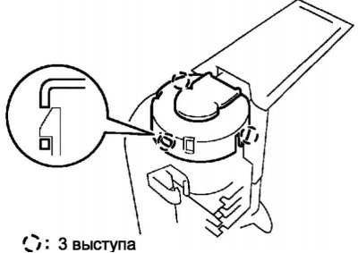
Pic. 2.512. Removing the support of the fuel intake No. 2
Use a screwdriver with a tape-wrapped blade to pry out the 3 tabs on the tabs. Then remove the No. 2 fuel pickup support (pic. 2.512).
Note. This operation must be carried out carefully so as not to damage the No. 2 fuel inlet support and the fuel filter.
Removing the rubber gasket of the fuel pump
Pic. 2.513. Removing the rubber pad
Remove the rubber gasket from the fuel pump (pic. 2.513).
Removing the fuel pump
Pic. 2.514. Removing the fuel pump
Remove the fuel pump from the fuel filter (pic. 2.514).
Pic. 2.515. Fuel filter gasket
Remove the fuel filter gasket from the fuel pump (pic. 2.515).
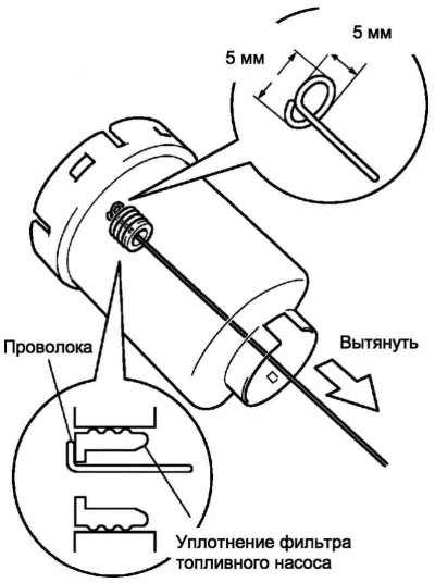
Pic. 2.516. Removing the fuel filter gasket
If the gasket remains inside the fuel filter, remove it with a wire with a diameter of 1 mm, bending its end, as shown in Figure 2.516.
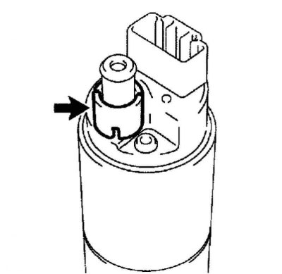
Pic. 2.517. Removing the fuel filter sleeve
Remove bushing from fuel pump (pic. 2.517).
Removing the fuel pump filter
Remove the clip with a thin blade screwdriver.
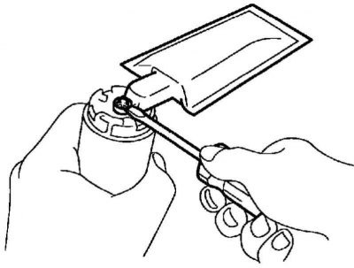
Pic. 2.518. Removing the filter
Remove filter from fuel pump (pic. 2.518).
Installing the fuel pump filter
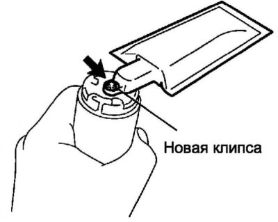
Pic. 2.519. Installing a new filter
Install the fuel pump filter with a new clip (pic. 2.519).
Fuel pump installation
Install the bushing to the fuel pump.
Install a new fuel pump filter gasket to the fuel pump.
Installing the fuel pump rubber gasket
Install the rubber gasket to the fuel pump.
Installation of the support of the fuel intake No. 2
Pic. 2.520. Installation of the support of the fuel intake No. 2
Align the tab with the cutout, then install the No. 2 fuel pickup support on the fuel filter (pic. 2.520).
Installing the Fuel Pressure Regulator Assembly
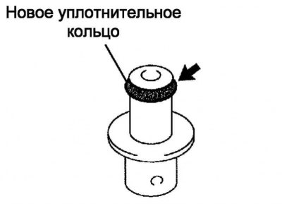
Pic. 2.521. Installing a new sealing ring
Lubricate the O-ring with fuel or spindle oil, then install the O-ring on the pressure regulator (pic. 2.521).
Lubricate the pressure regulator o-ring again with fuel or spindle oil, then insert the pressure regulator into the fuel filter.
Note. During installation, be careful not to damage or pinch the O-ring.
Installing the Fuel Pump Harness
Connect the ground terminal to the fuel filter.
Connect the fuel filter harness connector.
Installing the fuel pickup plate assembly
Lubricate the new O-ring with fuel or spindle oil, then install the O-ring on the fuel pickup plate.
Lubricate the O-ring of the fuel intake plate again with fuel or spindle oil. Align the tab with the cutout, then install the fuel pickup plate on the fuel filter.
Note. During installation, be careful not to damage or pinch the O-ring.
Connect the fuel pump connector.
Installing the Fuel Level Sensor Assembly
Pic. 2.522. Installing the fuel level sensor
Move the fuel level sensor until the protrusion locks into place (pic. 2.522).
Connect the fuel level sensor connector.
Installing the fuel intake with pump and fuel level sensor assembly
Install a new gasket to the fuel intake with fuel pump and fuel level sensor assembly.
Install the fuel intake assembly with the fuel pump and fuel level sensor in the fuel tank.
Note. This operation must be carried out carefully so as not to damage the fuel pump filter.
Note. Be careful not to bend the sensor arm.
Pic. 2.523. Alignment mark on the mounting plate of the vent tube of the fuel tank
Align the mark on the fuel tank vent tube mounting plate with the fuel pickup with the fuel pump and fuel gauge assembly (pic. 2.523).
Tighten 8 bolts.
Tightening torque: 6.0 Nm.
Connect the fuel supply line to the fuel tank.
Insert the connecting pipe into the fuel intake plate, then install the clamp.
Note. Before assembling, make sure that the parts to be joined are not damaged and free of foreign particles.
Note. Make sure the connecting tube is securely inserted into the plate.
Note. Make sure the clamp is in place where the fuel lines meet.
Note. After installing the clamp, pull on the piping to make sure the connection is secure.
Connect the negative terminal to the battery terminal.
Tightening torque: 5.4 Nm.
Check for fuel leaks.
Note. Check the fuel system for leaks after connecting the fuel pump connector.
Installing the rear service port cover
Apply new butyl tape to the rear access port cover.
Connect the fuel pump connector.
Install the rear service port cover by aligning the notches on the cover with the 2 tabs on the floor.
Note. Make sure the rear floor access hole cover does not rest against the floor panel tabs when installing.
Lay out the front and rear floor mats.
Note. Install other components in the reverse order of removal.