
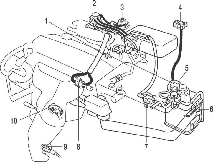
Pic. 7.28. Arrangement of elements of system of catching of vapors of fuel (EVAP) on models up to 2001: 1 - valve for forced ventilation of the crankcase; 2 - vacuum modulator of the exhaust gas re-burning system; 3 - valve of the exhaust gas re-burning system; 4 - fuel vapor pressure sensor; 5 - vacuum valve of the fuel vapor pressure sensor; 6 - container with activated carbon; 7 - vacuum valve of the fuel vapor recovery system; 8 - oxygen sensor (block 1 sensor 2); 9 - vacuum valve of the exhaust gas re-burning system; 10 - oxygen sensor (block 1 sensor 1)
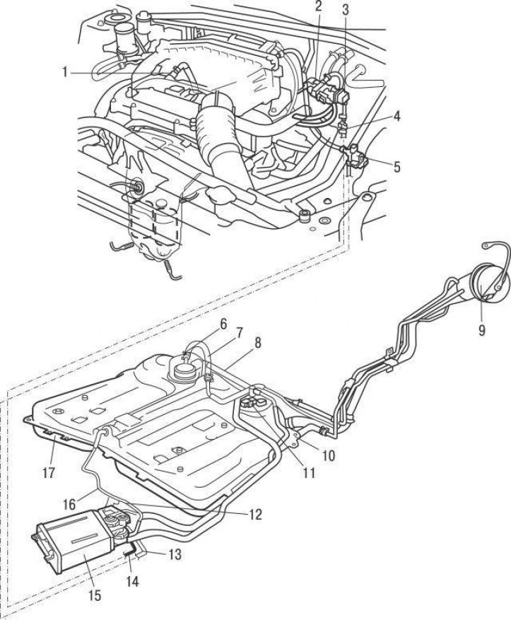
Pic. 7.29. Arrangement of elements of system of catching of vapors of fuel (EVAP) on models since 2001: 1 - valve for forced ventilation of the crankcase; 2 - vacuum valve of the fuel vapor recovery system; 3 - leveling tank; 4 - service connector of the fuel vapor recovery system; 5 - vacuum valve of the valve for closing the canister with activated carbon (CCV); 6 - fuel valve; 7 - pressure control tube; 8 - ventilation tube; 9 – a cover of a jellied mouth of a fuel tank; 10 - return hose; 11 - fuel vapor pressure sensor; 12 - vacuum valve controlling the pressure valve; 13 - hole for air supply; 14 – cleaning hose; 15 - canister with activated carbon; 16 - hose of the fuel vapor control system; 17 - fuel tank
On models since 2001, the activated charcoal container is installed in the engine compartment, and on models up to 2001, under the car, behind the fuel tank (pic. 7.28, 7.29).
When the engine is not running, fuel vapors are transferred from the fuel tank, throttle assembly, and intake manifold to the activated charcoal tank, where they are collected. After starting the engine, fuel vapors are removed from the tank through the cleaning control valve and fed into the engine cylinders for combustion. The purge control valve is controlled by the engine control unit.
The fuel filler cap has a double acting check valve. In the event of a malfunction in the fuel vapor recovery system, and an increase in pressure in the fuel tank, the valve releases fuel vapors into the atmosphere.
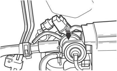
Pic. 7.30. Location of the fuel vapor pressure sensor on models up to 2001 of release
The evaporative emission system includes a pressure sensor (pic. 7.30), which responds to changes in fuel vapor pressure. On models prior to 2001, the sensor is mounted on the bulkhead of the engine compartment, and on models since 2001, on the top of the fuel tank on the fuel pump/sensor assembly.
After starting the engine and warming it up to the preset temperature, the vacuum valve (VSV) opens, opening the purge valve, causing the vacuum created in the intake manifold to draw fuel vapor out of the activated charcoal canister. Next, the fuel vapors are mixed with the air entering the engine and burned together with the fuel mixture in the engine cylinders.
A fuel vapor pressure sensor located in the fuel tank monitors the vapor pressure in the fuel tank and, when the pressure exceeds a preset threshold, the vacuum valve opens and fuel vapor exits the tank and collects in the activated charcoal canister.
To replace the activated charcoal container, proceed as follows:
- turn off the ignition and disconnect the wire «masses» from the storage battery;
- on models from 2001, raise the rear of the vehicle and secure it to supports;
- mark and disconnect all electrical connectors and hoses from the activated carbon container;
- unscrew the bolts and remove the container from the engine compartment or from under the car.
Install in the reverse order of removal.