
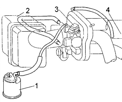
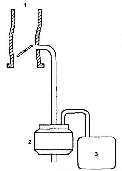
Diagram of vacuum lines (EJ-DE)
1 - fuel vapor accumulator,
2 - air filter,
3 - intake absolute pressure sensor,
4 - cylinder head cover.
1. (EJ-DE) Check the ventilation of the fuel vapor accumulator valves.
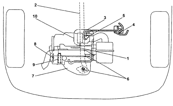
Location of elements of the electronic control system and fuel injection system (EJ-VE).
1 - hose of the crankcase ventilation system,
2 - front exhaust pipe of the exhaust system,
3 - electropneumatic valve,
4 - fuel vapor accumulator,
5 - intake air pressure sensor,
6 - oxygen sensor,
7 - exhaust manifold (with catalytic converter),
8 - crankshaft position sensor,
9 - asterisk of the DVVT system,
10 - elements of electronic control and injection systems.
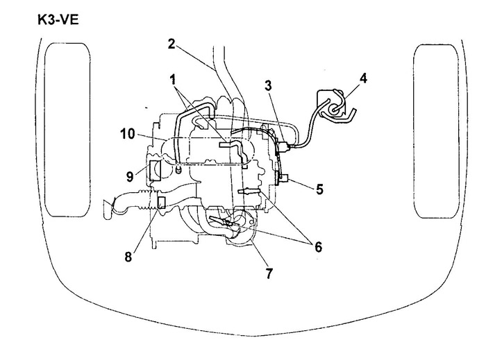
Location of elements of the electronic control system and fuel injection system (KZ series).
1 - hose of the crankcase ventilation system,
2 - front exhaust pipe of the exhaust system,
3 - electropneumatic valve,
4 - fuel vapor accumulator,
5 - intake air pressure sensor,
6 - oxygen sensor,
7 - exhaust manifold (with catalytic converter),
8 - crankshaft position sensor,
9 - asterisk of the DVVT system,
10 - elements of electronic control and injection systems.
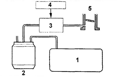
Fuel Paresis System (EJ-DE).
1 - throttle body,
2 - fuel vapor accumulator,
3 - fuel tank.
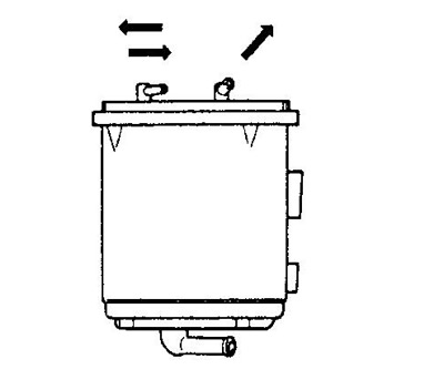
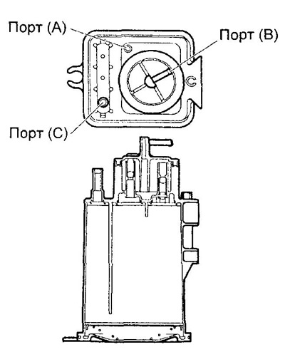
2. Check fuel vapor accumulator.
Evaporative Emission System (EJ-VE, KZ series).
1 - fuel tank,
2 - fuel vapor accumulator,
3 - electropneumatic valve,
4 - ECU,
5 - throttle body.
A) plug port (WITH) finger and pressurize the port (IN).
Make sure there is circulation between the ports (IN) And (A).
b) plug port (WITH) finger and apply a vacuum to the port (IN).
Make sure there is circulation between the ports (IN) And (A).
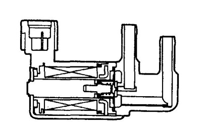
3. Check the electro-pneumatic valve.
A) Make sure there is no circulation between the ports.
b) Apply battery voltage to the solenoid valve terminals.
Make sure there is circulation between the ports.
V) Check the resistance between the solenoid valve terminals.
- Rated resistance (at 20°C) - 32 ohm
KZ series.
EJ series.