
General information
Typical EVAP System Component Layout
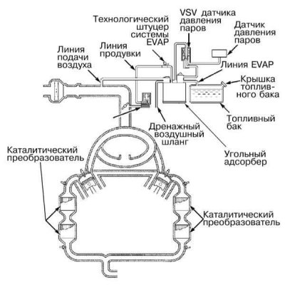
The EVAP system accumulates fuel vapors accumulated in the fuel system while the vehicle is parked and ensures that they are discharged into the intake tract for combustion during normal engine operation (refer illustration above). Improvement of the system is carried out continuously as the requirements for environmental protection become more stringent.
On early models, the EVAP system consisted of a charcoal canister equipped with a control valve and communication lines connecting it to the vehicle's fuel tank. The system also included a coolant temperature sensor (EATING), vacuum switch valve (VSV) and control module (ECM). On models of recent years of production, the system also includes a fuel vapor pressure sensor mounted on the rear bulkhead of the engine compartment. The layout of the components is shown on illustrations. The pressure sensor monitors pressure changes in the system associated with the development of leaks. The components to be monitored include the fuel tank, all vacuum lines connected to the adsorber and the throttle body. EVAP is part of the OBD-II on-board diagnostic system (see Sections On-Board Diagnostic System (OBD) - the principle of operation and fault codes and Information sensors - general information and function check) and to check the serviceability of its functioning on models of recent years of production, respectively, a special scanner is required.
Note. The composition of the EVAP system may vary depending on the model year. The layout of the vacuum hoses is presented on a special VECI information label, fixed in the engine compartment of the car.
While the car is parked, fuel vapors are removed from the cavities of the gas tank and the throttle body to the carbon adsorber, where they are accumulated until the engine is started. When the engine starts to rotate, the adsorber is purged and its contents are discharged into the intake pipe, from where it enters the combustion chambers.
The carbon adsorber is equipped with a control valve, the design of which includes two balls. Depending on the current operating conditions of the engine and the pressure in the fuel tank, the valve opens and closes, regulating the process of removing fuel vapors from the tank and the throttle body.
Examination
Note. A complete diagnosis of the EVAP system is one of the procedures that is beyond the skill of the average amateur mechanic and should be entrusted to a car service specialist. Note that system components are subject to additional federal warranties. Most often, EVAP system failures are due to damage to the carbon canister or connecting lines.
Violation of the stability of the idling speed, a decrease in the efficiency of the engine's return, spontaneous shutdowns of the latter can be caused by a failure of the control valve, damage to the carbon adsorber or connecting hoses of the EVAP system, as well as improper laying of the latter. Also check the condition of the fuel filler cap.
Obvious loss of fuel, as well as the appearance of a strong smell of fuel during parking, can be caused by leaking fuel lines, or damage to the charcoal canister body, a malfunctioning control valve, disconnected or obstructed evaporator lines, or improper laying of the latter.
1. Check the condition, route, and connection of all EVAP system hoses. Make any necessary repairs or replacements. Damaged components.
2. Inspect the bottom of the adsorber for signs of leaks, replace if necessary, make sure the hoses are connected correctly.
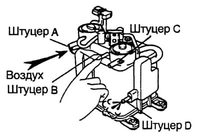
3. Disconnect the vacuum hoses from the top of the adsorber (refer to accompanying illustration). Close fittings A, B and C and supply air with a pressure of not more than 0.1 atm. to port D. Check that no air escapes from port F.
4. Create vacuum (no more than 0.1 atm.) on port C and check that it does not fall when port F is opened.
5. By closing the fitting F, create a vacuum (no more than 0.1 atm.) on port D and check that it does not fall when port C is closed and falls when open.
6. A defective adsorber must be replaced.
Replacing the carbon adsorber
1. Having previously carefully marked, disconnect all vacuum lines from the adsorber.
2. Turn out fixing bolts and remove assembly of an adsorber.
3. Installation is carried out in the reverse order.