



Checking and adjusting valve clearances

Please note: These models are equipped with airbags. Always lock the SRS when you are going to work in the immediate vicinity of its components to prevent the possibility of accidental airbag deployment, which could result in serious injury (see chapter 12).
Note: You will need a special tool to perform the following procedure if you are adjusting the clearances without removing the camshafts. An alternative to this is to make adjustments by removing the camshaft (camshafts), having previously measured the gaps (see below).
Examination
1. Disconnect the ground (-) terminal from the battery.
2. Remove the valve cover as described in chapter 2B.
3. While turning the crankshaft, install the intake camshaft so that the working projections of its cams above the intake valves of cylinder No. 1 are directed upwards, then, using a set of flat feeler gauges, measure the clearances between the cams and adjusting washers. Record the measurement results that do not meet the Specification standards. Next, turning the crankshaft, install the exhaust camshaft so that the working protrusions of its cams above the exhaust valves of cylinder No. 1 are directed upwards, measure the clearances and record the results of those measurements that do not meet the standards Specifications. These notes will be useful later for determining the thickness of newly installed adjusting washers. Measure the valve clearances of the remaining cylinders in the same order.
Adjustment
Note: All diesel engine models use special adjusting washers to adjust the clearance, which are installed on the top of the valve lifter.
4. If the gap size does not correspond to that specified in Specifications, it needs to be adjusted. While turning the crankshaft, set the camshaft so that the working protrusion of the cam above the valve to be adjusted is directed upwards in relation to the adjusting washer.
5. Turn the slot at the top of the tappet towards you to provide access to the adjusting washer, then install the tool ("pliers") as shown in the figure, squeeze them, overcoming the action of the valve spring. While holding the valve open in this manner, install the retaining "foot." Remove the adjusting washer using a small screwdriver, magnet, or tweezers (needle-nose pliers) (see Figure 23.5, a-c).
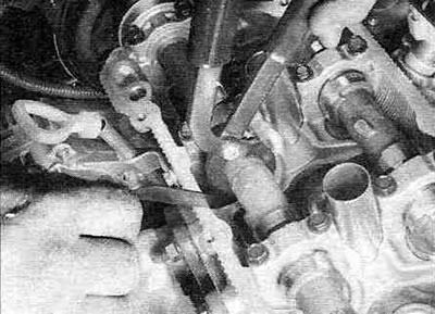
Figure 23.5,a. Install the clamping device and, squeezing the handles, press the pusher and then fix it.
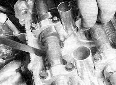
Figure 23.5, b. After securing the pusher, remove the adjusting washer using a small screwdriver or...
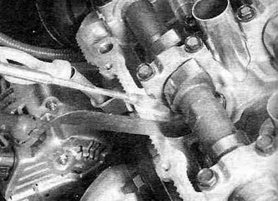
Figure 23.5, in... tweezers (needle-nose pliers) or a magnet, as shown in the picture.
6. If you do not have a wringer, you will have to remove one or more parts to adjust the gaps (if necessary) two camshafts (see chapter 2B).
(The original is published on the website www.ToyotaMan.ru)
7. Measure the thickness of the old adjusting washer with a micrometer (see Figure 23.7).
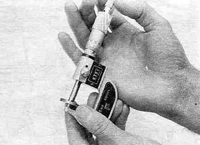
Figure 23.7. Measure the thickness of the adjusting washer with a micrometer.
To calculate the correct thickness of a new shim, use the formula:
N = T + (A - V), where:
N is the thickness of the new washer, T is the thickness of the old washer, A is the measured gap value, V is the required gap value (take from Specifications).
8. Select a new adjusting washer with a thickness that is closest to the value calculated using the formula provided.
Note: When replacing the adjusting washers, it is permissible to install (permutation) old washers - after measuring their thickness with a micrometer.
9. Install the wringer as described in point 5 (see Figure 23.5,a), then, pressing and fixing the pusher, install the new one (or a suitable old one) adjusting washer. Measure the gap with a feeler gauge to ensure the calculations are correct.
10. Repeat this procedure for all remaining valves whose clearance needs to be adjusted. If you have not used a wringer, follow the instructions in paragraph. 11.
11. Install the tappet with the replaced adjusting washer into place, having first lubricated them with the same grease that was used when installing the camshaft.
Note: Apply a thin layer of grease to the top of the tappet where it contacts the valve stem, the working surface, and the side surface of the tappet.
12. Install the camshaft (camshafts) (see chapter 2B).
13. Install the valve cover and everything else in the reverse order of removal.