
- Rotate the crankshaft until the piston of the first cylinder is in the TDC position. In this case, the mark on the pulley should coincide with the mark "0" on the scale on the housing cover.
- Check that the valve tappets of the first cylinder have slight play, and the valve tappets of the fourth cylinder are under tension. If this is not the case, turn the crankshaft one more revolution.
- Measure the valve clearances according to Figure 83 using feeler gauges inserted between the tappet and the cam surface. Intake clearances (E) and graduations (A) valves on both engines are different and are given in the tables of sizes and adjustments.
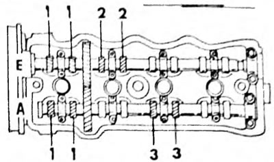
Pic. 83. Sequence of adjustment of the valves indicated by arrows when installing the piston of the first cylinder to the TDC position E - intake camshaft; A - exhaust camshaft
- Turn the engine one full turn and measure the clearances indicated in Figure 84.
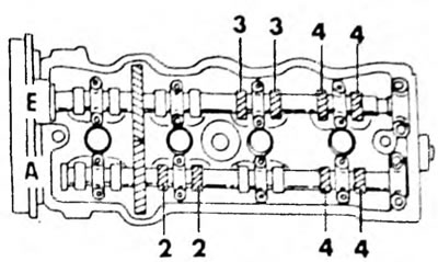
Pic. 84. Adjust the valve clearances indicated by arrows when installing the piston of the fourth cylinder to the TDC position E - intake camshaft; A - exhaust camshaft
- A sign of correct adjustment is that the end of the probe is inserted inward with resistance. The shims must be replaced to adjust the valve clearances, but a special tool is required to remove and install the shims. To do this, rotate the crankshaft until the corresponding cam is installed with the tip up and, using a special tool or otherwise, press the pusher so that you can pull out the adjusting washer with a small screwdriver. Before pressing the pusher, it should be turned so that the notch on top is facing the spark plugs.
The shim can be calculated using the following formula:
- Measure the removed washer with a micrometer (pic. 85) and write down the result.
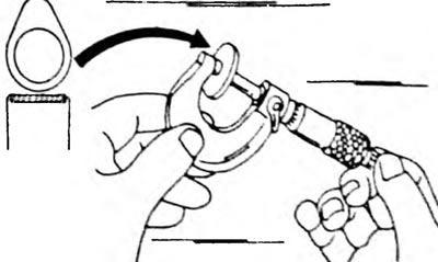
Pic. 85. Measuring the shim when adjusting valve clearances. The position of the adjusting washer relative to the pusher and the shaft cam is shown on the left
Calculate the thickness of the new washer to provide the required valve clearance. The following formula is used, but the engine type must be taken into account:
Engine 1.6 l (4A-F/FE)
Intake valves:
- N = T + (A - 0.20 mm)
Exhaust valves:
- N = T + (A - 0.25 mm)
Engine 2.0 l (3S-FE)
Intake valves:
- N = T + (A - 0.24 mm)
Exhaust valves:
- N = T + (A - 0.33 mm),
Where "T" - thickness of the removed washer, "A" - measured valve clearance and "N" - thickness of the new washer to be installed.
- Select a washer that is closest in thickness to the required gap. There is a range of 17 washer sizes with thicknesses ranging from 2.5mm to 3.3mm at 0.05mm intervals.
- To install the adjusting washer, press the pusher again and insert the washer.
- Measure the valve clearance as described above.
- Adjust the clearances of the remaining valves.
Do not allow the shim to fall into the engine. To avoid this, use a small screwdriver and a magnet, as shown in Figure 86. The washer should be pulled out to the side and "captured" magnet.
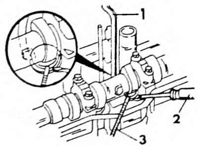
Pic. 86. Removing the adjusting washer when adjusting valve clearances. Press the pusher with a special tool (1) and remove the washer with a screwdriver (2) and a magnet (3)