



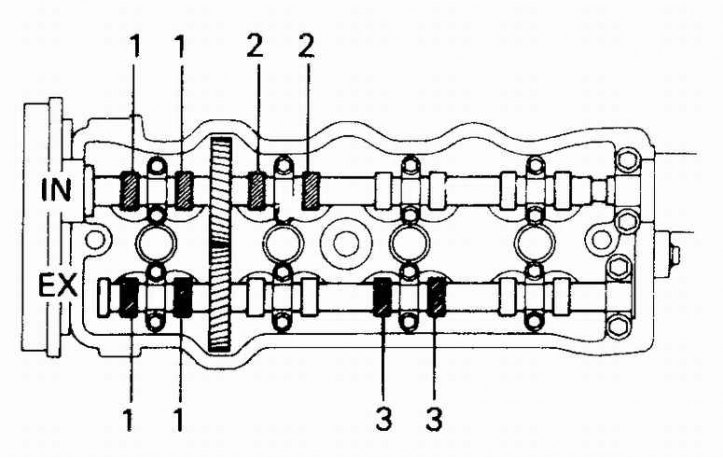
Clearances of the exhaust valves of the first and third cylinders and clearances of the intake valves of the first and second cylinders (four-cylinder engine)
Valve clearances (six-cylinder engine)
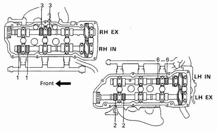
1. Right head, exhaust valves; 2. Right head, intake valves; 3. Left head, intake valves; 4. Left head, exhaust valves
4-cylinder engine valve clearances (the remaining)
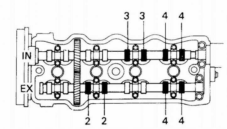
IN – Inlet valves
EX – Exhaust valves
Valve clearances of a 6-cylinder engine (the remaining)
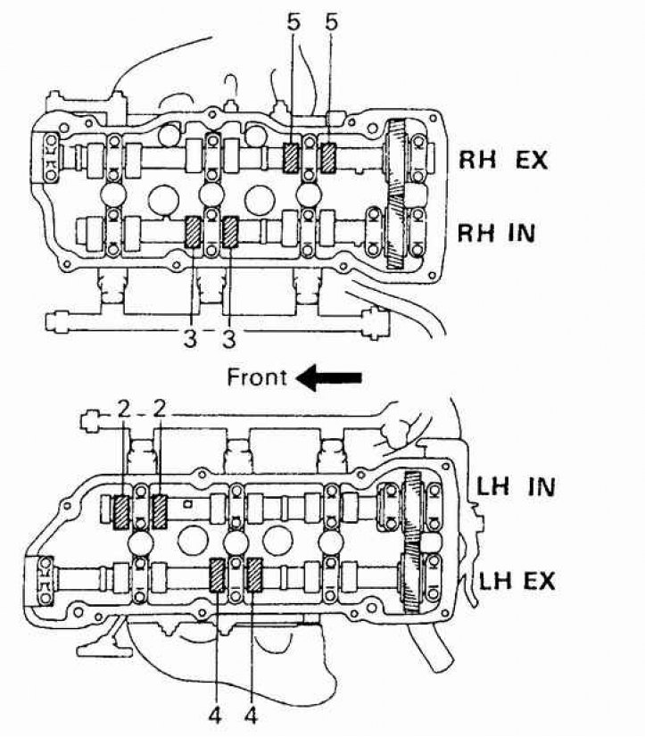
IN – Inlet valves
EX – Exhaust valves
Valve clearances of a 6-cylinder engine (the remaining) – 2
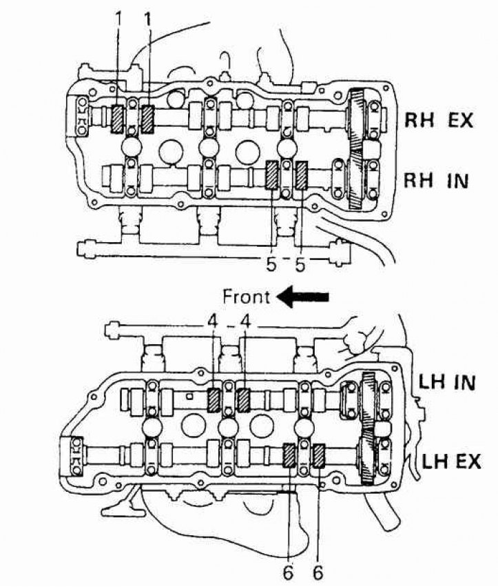
IN – Inlet valves
EX – Exhaust valves
1. Disconnect the negative battery cable.
2. On four-cylinder models, disconnect the spark plug wires.
3. On six-cylinder engines, drain the coolant and remove the air cleaner. Disconnect the rear bank spark plug wires and remove the front bank spark plug wires and coils.
4. Remove the spark plugs.
5. Remove the head cover.
6. Set the piston of cylinder N1 to the TDC position at the moment of the compression stroke.
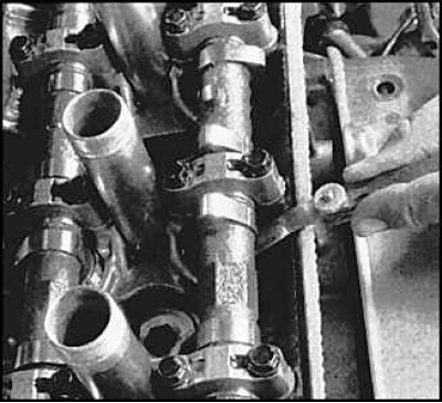
7. Measure the clearance of each valve using a set of feeler gauges.
8. On 4-cylinder models, rotate the crankshaft one full revolution and align the timing marks on the crankshaft pulley. Measure the remaining valve clearances (see fig. 4-Cylinder Engine Valve Clearances (the remaining)).
9. On models with a six-cylinder engine, turn the crankshaft 2/3 of a turn (240 degrees) clockwise. Measure the clearances of the indicated valves (see Fig. Valve clearances of a 6-cylinder engine (the remaining)). Turn the crankshaft another 2/3 of a turn and measure the clearances of the remaining valves (see Fig. Valve clearances of a 6-cylinder engine (the remaining) – 2).
10. Turn the crankshaft so that the cam above the valve requiring adjustment is raised up.
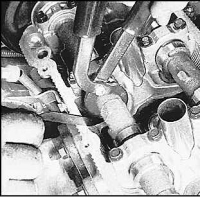
11. Turn the valve lifter so that the slot faces the spark plug. Install the tool and push the lifter. Compress the lifter with the special tool to remove the gasket.
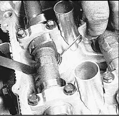 | 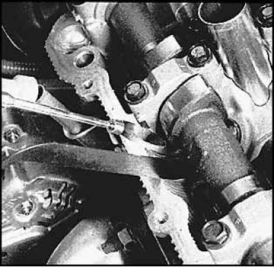 |
12. Remove the gasket using a small screwdriver or magnet.
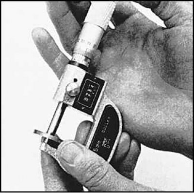
13. Measure the thickness of the gasket using a micrometer.
14. Calculate the required thickness of the new gasket using the following formula:
N = T + (A – V)
T = thickness of old washer
A = valve clearance
N = thickness of new washer
V = recommended valve clearance.
15. Install a new gasket and recheck the valve clearance.