
Note. On V6 models, the following procedure requires the use of a special pushrod tool. Perform this procedure without it is impossible.
1. Remove the right front fender apron, engine cover and all other elements that interfere with the removal of the cylinder head cover. Disconnect the wire from the negative battery terminal (see paragraph 1 of chapter 5).
2. Remove the coil (And) ignition.
3. On V6 models, drain the coolant (see paragraph 26), will remove the radiator inlet hose, air filter assembly, upper suspension tie rod, and all other items that interfere with the removal of the cylinder head cover.
4. If compressed air is available, blow out the spark plug recesses to remove any dirt that may have entered the cylinders, then remove the spark plugs (see paragraph 27).
Attention! Always wear eye protection when working with compressed air!
5. Remove the cover (And) cylinder heads (see chapter 2A or 2B).
6. Refer to chapter 2A or 2B and position the No. 1 piston at TDC on the compression stroke.
7. Measure the gap in the specified valves using a feeler gauge of the prescribed thickness (pic. 22.7, a, b, c). Record the gap value in each valve and note values that are out of tolerance. This information will be required later to determine the required shims or tappets.
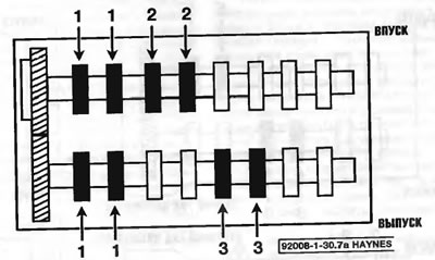
Pic. 22.7, a. On four-cylinder engines, when the No. 1 piston is at TDC on the compression stroke, the valve teasers can be measured in the exhaust valves of cylinders No. 1 and 3 in the intake valves of cylinders No. 1 and 2
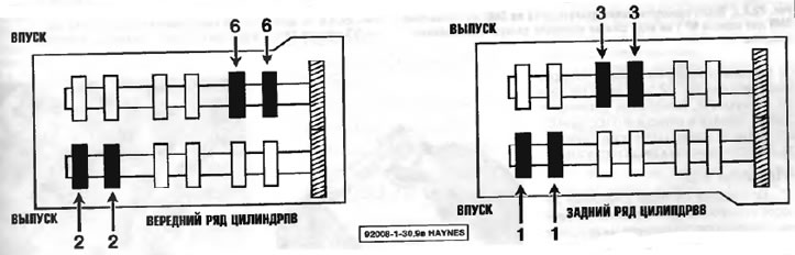
Pic. 22.7, b. On a V6 engine, with the #1 piston at TDC on the compression stroke, the valve clearances shown can be measured

Pic. 22.7, c. Measure the clearance in each valve with a feeler gauge of the prescribed thickness. If the clearance is correct, you should feel a slight resistance when inserting the probe
8. On four-cylinder engines, turn the crankshaft more than one full turn and align the timing marks again. Measure clearances in other valves (pic. 22.8).
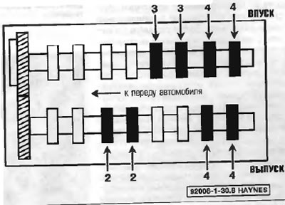
Pic. 22.8. On four-cylinder engines, when piston #4 is at TDC on the compression stroke, valve clearances can be measured at exhaust valves #2 and 4 and intake #3 and 4
9. On V6 engines, turn the crankshaft not ⅔ of a turn (240 degrees) clockwise. Measure the valve clearance on the valves shown (pic. 22.9, a). Turn the crankshaft not yet ⅔ of a turn and measure the clearance in the remaining valves (pic. 22.9, b).

Pic. 22.9, a. After cranking the V6 engine 240°from TDC for piston #1 on the compression stroke, measure the valve clearances shown
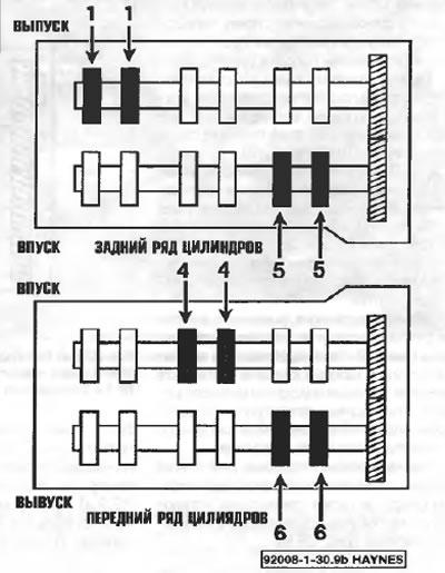
Pic. 22.9, b. On a V6 engine, turn the crankshaft an additional ⅔ turn (248°) and measure the gap in the remaining grooves
Four-cylinder models
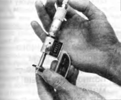
10. Remove the camshaft (s), corresponding to the valve (am), whose gaps you intend to adjust (see chapter 2A). Remove the pushrods one by one and measure the height of each with a micrometer (pic. 22.10). Before working with the next pusher, install the removed pusher back into its mounting hole in the cylinder head. Record the height of each pusher.
Pic. 22.10. In models with four-cylinder engines, measure the thickness of the pushrod with a micrometer
Models V6
11. On V6 models, after measuring the clearances in each valve and recording the results, turn the crankshaft pulley so that the camshaft cam above the first valve in which the clearance you intend to adjust is facing up away from the shim. Align the groove in the tappet in the direction of the spark plug. Then compress the pusher with special tools (pic. 22.11, a, b). Position the special tool in the required position as shown so that the longer tool jaw grips the lower edge of the cast boss on the pusher and the upper, shorter tool grip grips the top edge of the pusher itself. Compress the pusher by squeezing the handles of the tool, then hold the pusher down with the smaller tool and remove the larger tool. Remove the shim with a small screwdriver or tweezers (pic. 22.11, in). Be aware that the wire hook found at the end of some pushrod removal tool knobs can be used to squeeze the knobs together to hold the pushrod in the compressed position three times the shim is removed.
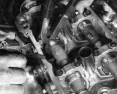
Pic. 22.11, a. On a V6 engine, install the pushrod puller as shown and squeeze its handles to compress the pushrod, then use a smaller tool to hold the pushrod pressed so the shim can be removed...
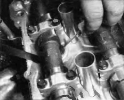
Pic. 22.11, b... continuing to press on the pusher, remove the shim with a small screwdriver...
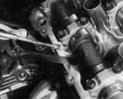
Pic. 22.11, in....tweezers or a magnet, as shown here
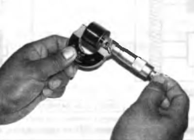
12. Measure the shim thickness with a micrometer (pic. 22.12)
Pic. 22.12. Measure the thickness of the shim with a micrometer
All models
13. To calculate the correct thickness of a replacement shim or tappet to correct valve clearance, use the following formula:
N = T + (A - V),
where T=thickness «old» shim or pusher;
A = measured valve clearance;
N = thickness of new shim or tappet;
V= desired valve clearance (see «Specifications»).
14. Select a shim or tappet whose thickness (whom) closest to the calculated valve clearance. Shims for V6 models are available in 17 thicknesses in 0.050 mm increments ranging from 2.500 mm to 3.300 mm. Tappets for four-cylinder engines are offered in 35 thicknesses with a resolution of 0.020 mm ranging from 5.060 mm to 5.740 mm.
Note. As a result of careful analysis of the shim or tappet dimensions that are needed to correct abnormal valve clearances, it is often possible to simply move the shim or tappet from one broom to another tappet where a shim or tappet of that particular size is required.
15. On V6 models, install the special pusher tool in the position shown (pic. 22.11, in) so that the longer tool grip grabs the lower edge of the cast boss on the pusher, and the upper, shorter tool grip grabs the top edge of the pusher itself. Compress the pushrod while squeezing the tool handles and install a new shim. A wire hook found at the end of some pushrod removal tool knobs can be used to press the knobs together to hold the pushrod in a compressed position when installing the shim. Measure the gap with a feeler gauge to make sure the calculations are correct.
16. Repeat this procedure on all valves that require valve clearance adjustment.
17. Installation of spark plugs, cylinder head cover, camshaft (ov), accelerator cable bracket, etc. is performed in the reverse order of removal.
18. Not models with four-cylinder engines, after installing the camshafts, check the valve clearances again to make sure they are correct.