



Ignition coil(s) (gasoline engines)
Examination
Note 1: Specification data is not available for checking the ignition coil primary resistance on 1998-2000 models, or for checking the ignition module/coil assembly resistance on 2001-onward models.
Note 2: The following checks should be performed with the engine cold. When the engine is warm, the resistance value will be higher.
1. Check the resistance of the primary winding of the ignition coil. Turn the ignition key to the OFF position, disconnect the wiring connector(s) from all ignition coils. Connect an ohmmeter to the terminals of the primary winding of the coil (see Figure 7.1).
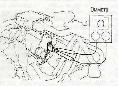
Figure 7.1. Checking the resistance of the primary winding of the ignition coil - 1996 and 1997 models.
The resistance value must comply with the specifications in this chapter, otherwise the coil must be replaced.
2. Check the resistance of the secondary winding of all ignition coils. Turn the ignition key to the OFF position, label and disconnect the high voltage wires from all coils. Connect an ohmmeter to the secondary winding terminals of each coil (see figure 7.2,a,b).
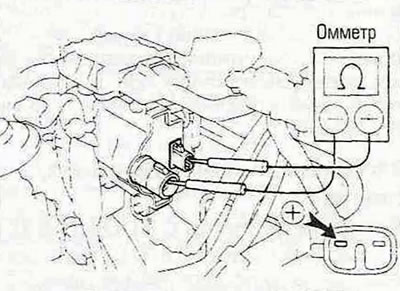
Figure 7.2,a. Checking the resistance of the secondary winding of the ignition coil - 1996 and 1997 models.
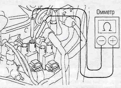
Figure 7.2.6. Checking the resistance of the secondary winding of the ignition coil - models produced in 1998-2000.
The resistance value must correspond to the prescribed one Specification this chapter, otherwise the coil must be replaced.
Removal and installation
3. Disconnect the cable from the negative battery terminal.
Models produced in 1996 and 1997
4. Disconnect the wiring connector from the ignition coil. Disconnect the center wire.
5. Loosen the bracket mounting bolts and separate the bracket/ignition coil assembly from the engine (see Figure 7.5).
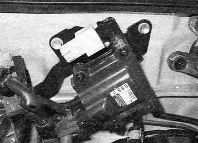
Figure 7.5. The bracket with the ignition coil in 1996-1997 models is installed in the engine compartment on the engine shield.
6. Loosen the bolts securing the ignition coil to the bracket and remove the coil.
7. Install the ignition coil in the reverse order of its removal.
Models produced in 1998-2000
8. Remove the throttle body from the intake manifold (see chapter 4A).
9. Remove the cover from the air filter housing (see Chapter 1A).
10. Disconnect the wiring connector(s) from each coil. Label the connectors to avoid confusion during installation. Mark and disconnect the high voltage wires.
11. Loosen the ignition coil bracket mounting bolts and remove it from the engine (see Figure 7.11).
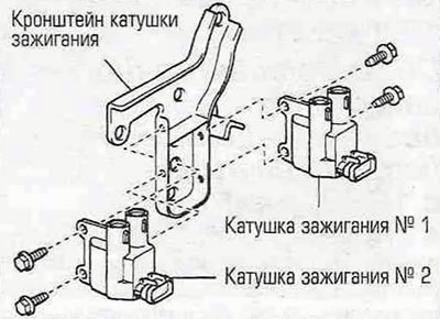
Figure 7.11. Ignition coils in models; produced in 1998-2000, they are mounted on a bracket on the left side of the head; cylinder block.
12. Separate the coils from the bracket.
13. Install the ignition coils in the reverse order of their removal.
Models produced since 2001
14. Remove the front half of the air filter housing (see Chapter 1A).
15. Each ignition coil/module assembly is secured with one bolt. Loosen the bolt, disconnect the wiring connector and pull the assembly straight up, twisting it left and right.
16. Install the components in the reverse order of their removal.