
- A) The engine is warmed up to normal operating temperature.
- b) Air filter installed
- V) All tubes and hoses of the air intake system are connected
- G) All vacuum lines are connected.
- d) The injection system wiring connectors are connected.
- e) All additional equipment is off
- and) The ignition timing is set correctly.
- h) Gear lever in neutral position.
Note: The test is only used to ensure that the mixture is adjusted correctly at idle (according to the content of CO and CH in the exhaust gas).
2. (Only 3S-GE, 5E-FE) Check the operation of the oxygen sensor.
- A) Use a jumper to bridge the leads "TE1" And "E1" diagnostic socket.
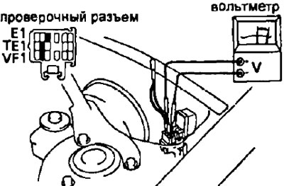
- b) Connect positive (+) output voltmeter probe "VF1" diagnostic connector, and negative (-) output probe "E1".
- V) Set the engine speed to 2500 rpm and hold it for 120 seconds.
- G) The voltmeter needle should then fluctuate between 0 and 5 V.
- Minimum oscillation of the voltmeter needle: 8 times for every 10 seconds.
- If the fluctuation is less than expected, check the air intake or injection system.
- d) Remove the jumper from the diagnostic socket.
3. Start the engine.
4. Increase engine speed to 2500 rpm and maintain this speed for approximately 120-180 seconds
5. Insert the gas analyzer probe into the exhaust pipe to a depth of 40 cm
6 Check the CO/CH concentration at idle.
- CO concentration at idle - 0-0.5%