
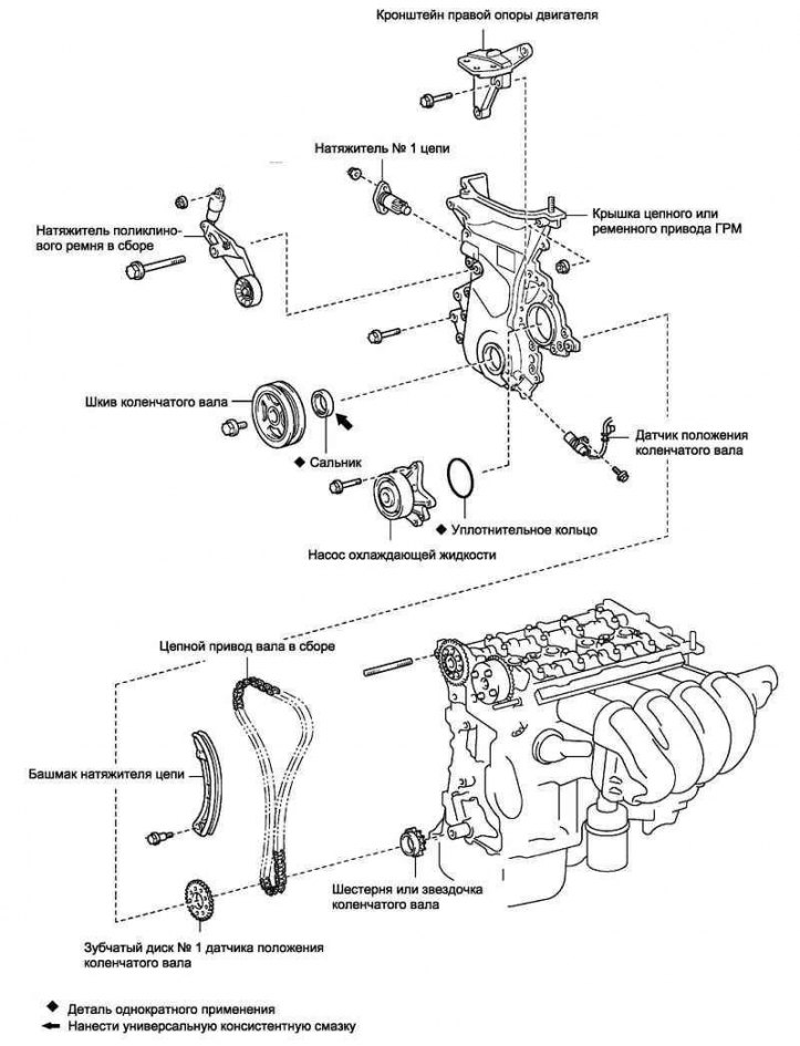
Pic. 2.121. Timing chain components
The components of the timing chain are shown in fig. 2.121.
Removal of a pillow of the right support of the engine
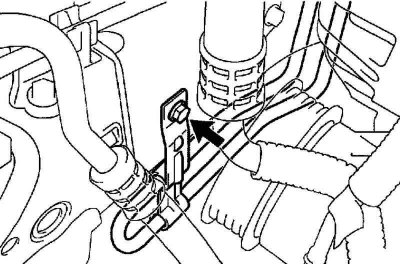
Pic. 2.122. Bolt of fastening of an arm of the pipeline of the return discharge of fuel
Remove the bolt, then disconnect the fuel return line (pic. 2.122).
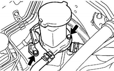
Pic. 2.123. Bolts of fastening of an arm of an oil tank No. 1
Remove the 2 bolts, then disconnect the #1 oil tank bracket (pic. 2.123).
Place a block of wood on the jack and place the jack under the engine.
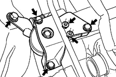
Pic. 2.124. Bolts and nuts of fastening of a pillow of the right support of the engine
Turn out 4 bolts and turn off 2 nuts, then remove a pillow of the right support of the engine (pic. 2.124).
Removing the ignition coil
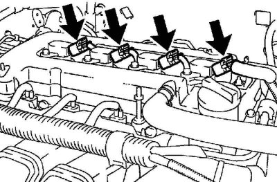
Pic. 2.125. Ignition coil connectors
Disconnect the 4 ignition coil connectors (pic. 2.125).
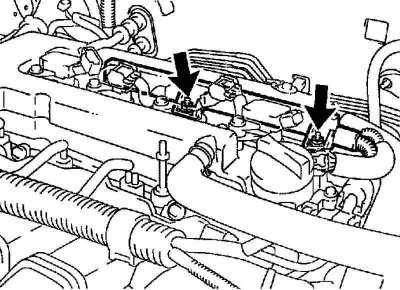
Pic. 2.126. Nuts of fastening of a plait of wires of the engine
Remove the 2 nuts, then remove the engine wiring harness (pic. 2.126).
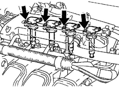
Pic. 2.127. Ignition coil bolts
Remove 4 bolts, then remove 4 ignition coils (pic. 2.127).
Removing the cylinder head cover
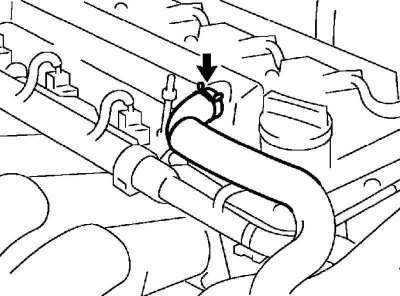
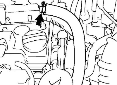
Pic. 2.128. crankcase breather hose
Disconnect the crankcase ventilation hose from the cylinder head cover (pic. 2.128).
Pic. 2.129. Hose No. 2 of the crankcase ventilation system
Disconnect hose No. 2 of the crankcase ventilation system from the valve of the crankcase ventilation system (pic. 2.129).
Remove the 3 clamps of the engine wiring harness from the bracket.
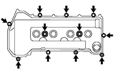
Pic. 2.130. Fastening of a cover of a head of the block of cylinders
Remove 9 bolts, remove 2 sealing washers, remove 2 nuts, remove 3 mounting brackets, then remove the cylinder head cover (pic. 2.130).
Removing the V-ribbed belt tensioner assembly
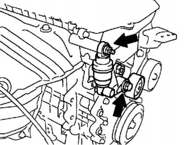
Pic. 2.131. Poly V-belt tensioner mounting
Remove the bolt and nut, then remove the V-ribbed belt tensioner (pic. 2.131).
Note. To remove the bolt, move the tensioner up and down.
Removal of an arm of the right support of the engine
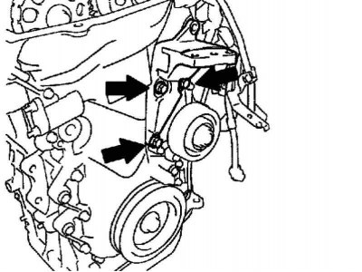
Pic. 2.132. Bolts of fastening of an arm of the right support of the engine
Remove 3 bolts, then remove right engine mount bracket (pic. 2.132).
Remove the coolant pump assembly.
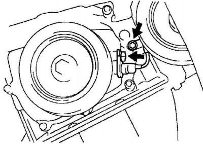
Pic. 2.133. Bolts of fastening of the gauge of position of a cranked shaft
Remove 2 bolts and disconnect crankshaft position sensor (pic. 2.133).
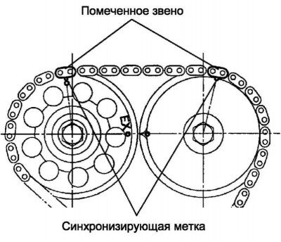
Setting the piston of cylinder No. 1 to TDC of the compression stroke
Turn the crankshaft pulley and align the mark on it with the timing mark «0» on the timing chain cover.
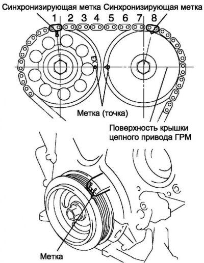
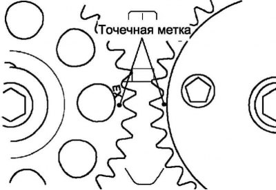
Pic. 2.134. Installing the piston of cylinder No. 1 at TDC of the compression stroke
Make sure the labels (points) on the gears of the camshaft drive are located opposite each other, as shown in Figure 2.134.
Otherwise turn the crankshaft 1 turn (360°) and align the marks as above.
Removing the crankshaft pulley
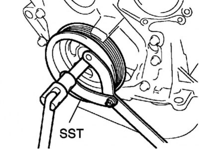
Pic. 2.135. Removing the crankshaft pulley
Using SST 09960-10010 (09962-01000, 09963-01000) remove the crankshaft pulley bolt (pic. 2.135).
Remove the pulley from the crankshaft.
Removing the chain tensioner No. 1
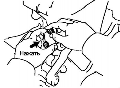
Pic. 2.136. Removing the tensioner No. 1
Loosen the 2 nuts, then remove the chain tensioner (pic. 2.136).
Note. It is forbidden to rotate the crankshaft if the chain is not tensioned with the tensioner.
Removing the timing chain or belt drive cover
Remove 10 bolts and 2 nuts.
Remove the stud using a TORX E8 socket wrench.
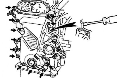
Pic. 2.137. Timing cover bolts
Separate the timing cover by inserting a screwdriver between the cover, cylinder head and cylinder block (pic. 2.137).
Note. Be careful not to damage the mating surfaces of the timing cover, cylinder block and cylinder head.
Extraction of an epiploon of a cover of a chain or belt drive GRM
Install the timing cover on the wooden blocks.
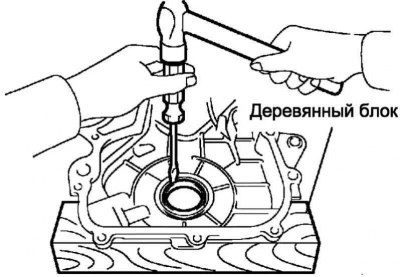
Pic. 2.138. Oil seal removal
Remove the seal with a screwdriver (pic. 2.138).
Removing the toothed disk of the crankshaft position sensor No. 1

Pic. 2.139. Tooth disk of the crankshaft angle sensor
Remove the gear disk of the crankshaft angle sensor from the crankshaft (pic. 2.139).
Removing the chain tensioner shoe
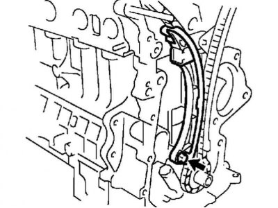
Pic. 2.140. Bolt of fastening of a shoe of a tensioner of a chain
Unscrew the bolt and remove the chain tensioner shoe (pic. 2.140).
Removing the chain assembly
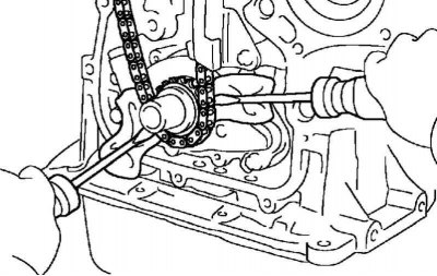
Pic. 2.141. Removing the chain
Using 2 screwdrivers, remove the chain together with the drive gear, as shown in Figure 2.141.
Note. Place a rag under the screwdriver so as not to damage the engine.
If it is necessary to rotate the camshafts with the chain removed from the gears, the crankshaft must be rotated 1/4 turn to avoid contact between the valves and the pistons.
Installing the complete chain
Set the #1 cylinder piston to TDC on the compression stroke.
Pic. 2.142. Alignment of marks on drive gears
Turn the camshafts at the hexagon so that the 2 marks (points) on the drive gears are located opposite each other (pic. 2.142).
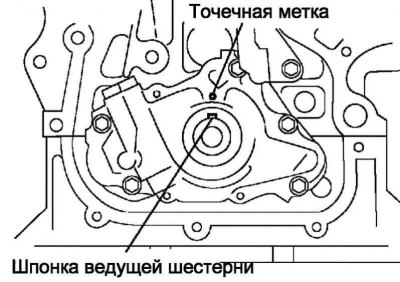
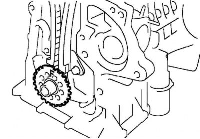
Pic. 2.143. Aligning the timing gear key with the dot mark on the oil pump
Turn the crankshaft at the crankshaft pulley bolt so that the timing gear key is aligned with the dot mark on the oil pump (pic. 2.143).
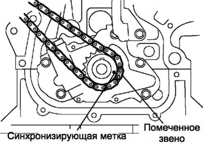
Pic. 2.144. Aligning the link with the yellow mark with the timing mark on the gear
Install the chain on the timing gear, aligning the yellow mark link with the timing mark on the timing gear (pic. 2.144).
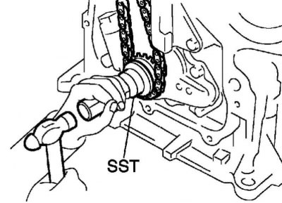
Pic. 2.145. Installing the timing gear on the crankshaft
Using SST 09223-22010, install the timing gear to the crankshaft (pic. 2.145).
Pic. 2.146. Alignment of links with a yellow mark with timing marks on the camshaft gears
Install the timing chain on the camshaft gears, aligning the links with the yellow mark with the timing marks on the camshaft gears (pic. 2.146).
Install the chain tensioner shoe and secure it with the bolt.
Tightening torque: 18.5 Nm.
Pic. 2.147. Label «F» on the toothed disk of the crankshaft angle sensor
Install the gear disk of the crankshaft angle sensor with the mark «F» to the front of the car (pic. 2.147).
Installing the oil seal of the timing chain or belt drive cover
Lubricate the seating surface of the new oil seal with a light coat of multipurpose grease.
Install the timing cover on the wooden blocks.
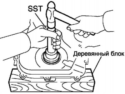
Pic. 2.148. Pressing in a new seal
Using SST 09223-22010, press in a new oil seal so that its surface is flush with the edge of the timing cover (pic. 2.148).
Note. The seating surface of the seal must be free of sand, dirt and other foreign particles.
Installing the timing chain or belt drive cover
Remove any old sealant from the mating surface.
Pic. 2.149. Sealing locations
Apply sealant in a continuous bead (diameter 3.5–4.5 mm), as shown in Figure 2.149.
Note. Clean mating surfaces of oil.
Install the oil pan within 3 minutes after applying the sealant.
Fill the engine with oil no earlier than 2 hours after installing the sump.
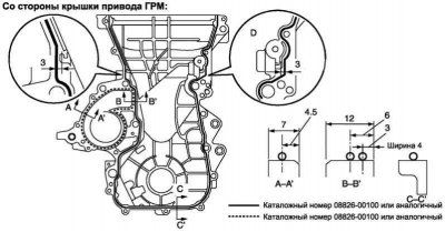
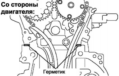
Pic. 2.150. Scheme of laying sealant on the side of the timing cover
Be especially careful to apply sealant in area D - no more than the indicated amount (pic. 2.150).
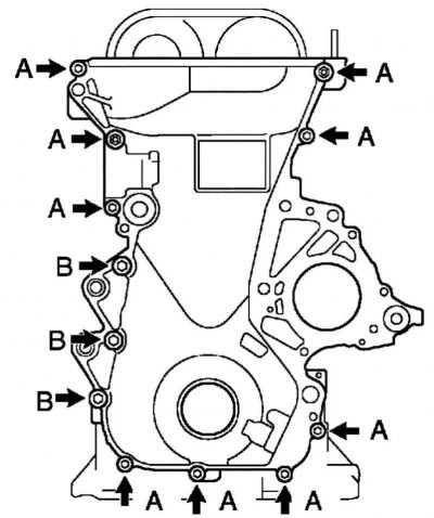
Pic. 2.151. Bolts and nuts for fastening the timing cover
Attach the timing chain cover with 10 bolts and 2 nuts (pic. 2.151).
Tightening torque: 13 Nm for bolt A and nut A, 18.5 Nm for bolt B.
Using a TORX E8 socket wrench, tighten the stud.
Tightening torque: 9.5 Nm.
Installing the chain tensioner assembly No. 1
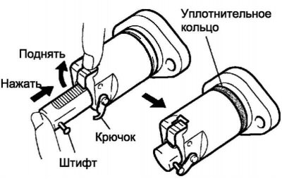
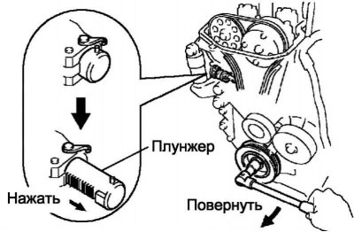
Pic. 2.152. Plunger fastening hook
Make sure that there is no dirt on the sealing ring, then install the hook, as shown in Figure 2.152.
Apply a thin coat of engine oil to the O-ring.
Secure the chain tensioner with 2 nuts.
Tightening torque: 9.0 Nm.
Note. Be careful not to crush the O-ring.
If, when installing the chain tensioner, the hook disengages and releases the plunger, re-secure the plunger with the hook.
Installing the crankshaft pulley
Align the key on the shaft with the groove in the pulley, then slide the pulley onto the crankshaft.
Using SST 09960-10010 (09962-01000, 09963-01000) tighten the crankshaft pulley bolts.
Tightening torque: 138 Nm.
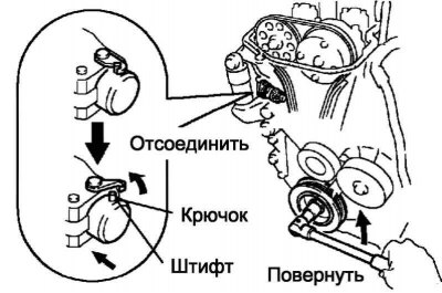
Pic. 2.153. The position of the crankshaft when removing the plunger
Turn the crankshaft counterclockwise, then remove the hook from the lock pin and release the plunger (pic. 2.153).
Pic. 2.154. Checking plunger operation
Rotate the crankshaft clockwise and check that the plunger presses on the chain tensioner shoe (pic. 2.154).
If the plunger does not extend, use a screwdriver to push the shoe towards the tensioner so that the hook disengages from the stop pin and the plunger can extend.
Installing the crankshaft position sensor
Apply a light coat of engine oil to the crankshaft position sensor O-ring.
Install the crankshaft position sensor with 2 bolts.
Tightening torque: 9.0 Nm.
Install the coolant pump assembly.
Install the right engine mount bracket.
Tightening torque: 47 Nm.
Install the V-ribbed belt tensioner assembly.
Installing the cylinder head cover
Remove any old sealant from the mating surface.
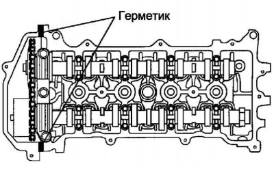
Pic. 2.155. Sealing locations
Apply sealant at 2 points, as shown in Figure 2.155.
Note. Clean mating surfaces of oil.
Note. Install the cylinder head cover within 3 minutes after applying the sealant.
Note. Fill the engine with oil not earlier than 2 hours after installing the cylinder head cover.
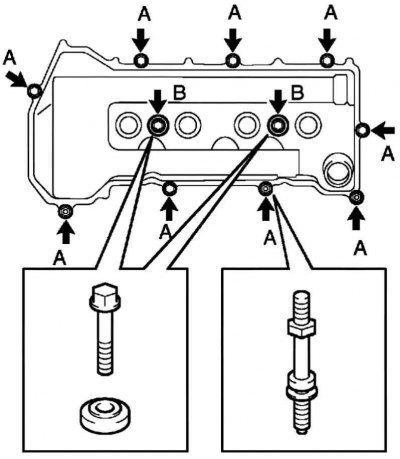
Pic. 2.156. Bolts and nuts of fastening of a cover of a head of the block of cylinders
Install the cylinder head cover and 3 mounting brackets with 9 bolts, 2 sealing washers and 2 nuts (pic. 2.156).
Tightening torque: 11 Nm for bolt A and nut A, 9.0 Nm for bolt B.
Install the 3 engine harness clamps to the brackets.
Attach hose No. 2 of the crankcase ventilation system.
Connect the crankcase ventilation hose.
Install the remaining components in the reverse order of removal.