



2. Arrange the rings in order according to the piston/cylinder numbering.
3. Install the upper compression ring into the first cylinder. Push it with the piston into the cylinder, placing it at the lower edge of the cylinder, at the limit of the piston stroke.
4. Measure the gap in the lock using a set of flat feeler gauges. The feeler gauge blade should enter the ring lock with a slight tension. Compare the results with the Specifications. New rings must have a lock no smaller than that specified in Specifications. It is unlikely that genuine Toyota parts are supplied defective; if the gap differs from the prescribed one or the ring does not fit into the cylinder, check whether you have purchased the right rings. It is highly unlikely that the gap in the locks of the new rings will be too large. Make sure you get the right size rings for the specific Toyota engine and model, and not for any other one.

Figure 20.4. After installing the piston ring into the cylinder, measure the gap of its ring joint using a set of flat feeler gauges.
5. If the gap in the ring lock is too small (which is unlikely for genuine Toyota parts), it needs to be expanded, otherwise, during engine operation, the ends of the ring will close, causing serious damage. Ideally, new piston rings should provide the required ring clearance and be ready to install. As a last resort, you can increase the gap by removing a little metal from the end of the ring with a thin file. Clamp the file in a vice with soft jaws and move the end of the ring along the file, holding it strictly perpendicular, removing the required amount of metal. Be careful - the ring is sharp and fragile.
6. It's also undesirable to have a larger gap than 1.0 mm on new rings. If the gap is too large, double-check that you purchased the correct ring size for your specific engine and cylinder size. The cylinder may be too worn or may have been bored incorrectly.
7. Repeat the clearance measurement procedure for all rings of the first cylinder, then for the rings of the remaining cylinders. Be sure to keep the rings and pistons together so they fit into the cylinders when assembled.
8. Now that all the rings have been checked and the clearances adjusted, they can be installed on the pistons.
9. When installing rings, the same technology is used as when removing them. First install the oil scraper ring spring into the third groove (see Figure 20.9,a).
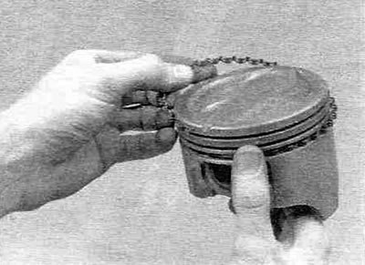
Figure 20.9,a. Install the oil scraper ring expander spring into the third groove of the piston...
If the expander spring has a retaining tab, hook it over the oil drain hole inside the groove. When installing a three-piece oil scraper ring, install the thin lower oil scraper ring with its lock offset by 120° relative to the expander lock, and the upper oil scraper ring with its lock offset by 120° relative to the lower ring lock. Install thin rings ("noodles") with your hands (see figure 20.9,6) - They can be broken with a tool.
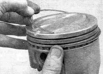
Figure 20.9, b....and then install the thin lower and upper oil scraper rings.
When installing a two-piece oil scraper ring, first install the expander spring, then the thin oil scraper ring, offsetting its end by 180° relative to the expander end. Next, install the second compression ring. Ensure the second compression ring is installed correctly with the "TOP" mark or dot facing up and the scraper facing down. Install the top compression ring last, also with the "TOP" mark facing up. Position the compression ring joints so that they are offset 120° from the oil scraper ring joints, but not above the piston pin bores (see Figure 21.5, a-c).
Note: Different piston ring manufacturers may provide different installation instructions - please follow their instructions. Do not mix up the compression rings - they can be distinguished by the shape of the cross-sections.