



2. Remove the cap from the lower end of connecting rod No. 1 (according to the marks made during removal). Remove the old bearings and thoroughly wipe the working surfaces of the connecting rod and its cap with a clean, lint-free cloth. Work surfaces must be absolutely clean.
3. Remove the protective coating from the back of the new bearing with kerosene and wipe with a clean, lint-free cloth, then place the bearing into the connecting rod head, aligning its lock with the recess in the connecting rod bed, and also aligning the oil passage holes. The insert is installed using only the force of your fingers, without the use of any tools. Be careful not to scratch the work surface. Do not apply lubricant.
4. Wipe dry the back surface of the other bearing and place it in the connecting rod head cap in the same manner. Do not apply grease - during assembly it is extremely important that the area between the bearing and the inner surface of the connecting rod head is perfectly clean.
5. Rotate the rings so that their locks are located at angles of 120° around the circumference of the piston (see figure 21.5, a-c).
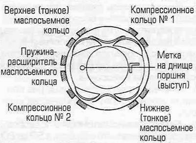
Figure 21.5,a. Location of piston ring locks - engines produced before 2000 with a working volume of 2.0 liters.
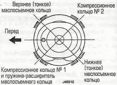
Figure 21.5,b. Location of piston ring locks - 2000 gasoline engines with a working volume of 1.8 liters.
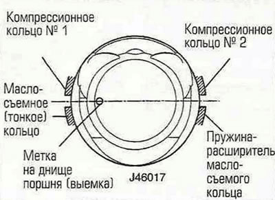
Figure 21.5, c. Location of piston ring locks - gasoline and diesel engines produced since 2001 with a working volume of 2.0 liters.
6. If possible, place pieces of plastic or rubber hose over the connecting rod cap bolts to avoid damaging the cylinder walls during assembly.
7. Thoroughly lubricate the pistons and rings with engine oil and put a ring compression compressor ("swage") on the piston. Leave the piston skirt protruding 8 mm from under the compressor. Squeeze the compressor rings so that they are completely "hidden" in the grooves of the piston.
8. Turn the crankshaft until its first journal is at BDC (bottom dead center). Generously lubricate the cylinder walls with engine oil.
9. Place the mark on the piston bottom (one or two teeth or projections) forward-facing engine (to the timing chain/belt), carefully insert the piston with the connecting rod into cylinder No. 1, being careful not to damage the cylinder walls. Place the compressor against the mating surface of the block.
10. Tap the compressor from above with a hammer to align its bottom edge with the mating surface of the block.
[The material is republished from an online website: www.ToyotaMAN.ru]
11. Lightly tap the bottom of the piston with the wooden handle of a hammer (see figure 21.11), directing the connecting rod towards the journal, push it into the block until the piston bottom is aligned with the block surface.
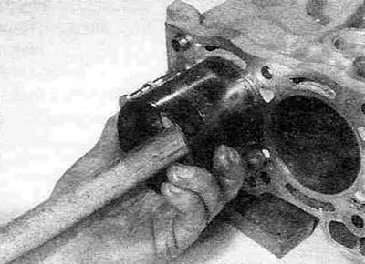
Figure 21.11. Using the hammer handle, push the piston into the cylinder.
Keep pressing the crimping tool against the block at all times. It's not speed that's needed here, but precision: as soon as you feel the piston moving impeded, stop hammering immediately; you'll break both the rings and the pistons. Before proceeding, find the cause and fix it. If the piston, rings and cylinder are sized correctly, there is enough lubrication and no special force is required - the piston enters the cylinder with noticeable friction, which can be overcome with the force of one hand.
Warning. Never use force when inserting the piston into the cylinder, otherwise you may break the rings and/or the piston.
12. After making sure that the connecting rod bearing surfaces are absolutely clean, lubricate them with clean engine oil. The piston will need to be pushed into the cylinder so that the bearing in the connecting rod can be lubricated.
13. Move the connecting rod towards the journal, remove the "socks" from the bolts and install the cover on the connecting rod. Make sure that the mark on the cover matches the mark on the connecting rod (what does it mean when the mounting protrusions of the bearings fit together?). Install the bolts/nuts and tighten them to the torques specified in Specifications, in two stages.
14. Using a wrench, tighten the bolts/nuts securing the covers to the torque specified in Specifications for the first pass, then turn them to the angle prescribed for the second pass.
15. Check the smooth rotation of the crankshaft by turning it a few revolutions by hand. If new parts are installed, the crankshaft may turn with a little effort, but the hand strength should be sufficient for this, there should be no jamming.
16. Install the remaining three piston/connecting rod assemblies in the same order.
Engines produced since 2001 with a volume of 2.0 liters
17. Make sure that the mating surfaces of the cylinder block and its lower crankcase are perfectly clean and dry, and place a new sealing ring in the groove on the mating surface of the cylinder block, made around the opening of the oil channel leading to the cylinder head.
18. Apply a 2.5-30 mm wide bead of sealant to the lower crankcase mating surface (Toyota part number 08826-00080 or equivalent) (see figure 21.18).
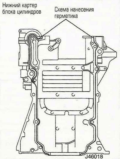
Figure 21.18. Apply a 2.5-3.0 mm wide bead of sealant to the mating flange of the lower crankcase of the engine block - gasoline engines produced since 2001 with a working volume of 2.0 liters.
Install the crankcase within three minutes of applying the sealant, before it hardens.
19. Thread the six short and five long mounting bolts into place and tighten them hand tight (see Figure 12.2,a). Working in a diagonal sequence, gradually tighten the bolts to the specified torque. Install the new crankshaft oil seal as described in Part B of this chapter.
All engines
20. Install the oil pump with oil receiver, engine oil pan (and the upper housing of the oil pan in diesel engines), engine rear cover, cylinder head, timing belt/chain, flywheel/faceplate and all remaining ancillary components as described in section A, B or IN this chapter.