



Note: Before removing the pistons and connecting rods, remove the cylinder head, oil pan and upper (aluminum) section of the oil pan (see chapter 2A or 2B). Also, on four-cylinder engines, remove the balancer shafts (see paragraph 9).
1. Check the cylinder surface with your fingernail to see if a ridge has formed on the upper edge of the ring movement zone during the reciprocating motion of the piston in the cylinder (approximately 6mm from the top of each cylinder). If carbon deposits or cylinder wear have caused a ridge to form, it should be completely removed using a special tool (Fig. 10.1). Follow the tool manufacturer's instructions. Failure to remove the ridges before removing the pistons and connecting rods may result in piston failure.
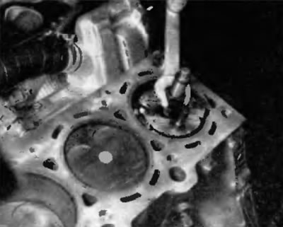
Fig. 10.1. Before removing the pistons, remove the ridges in the upper area of the cylinder using a suitable reamer
2. After removing the ridges in the cylinders, turn the engine over so that the crankshaft is on top.
3. Before removing the pistons with connecting rods, use a feeler gauge to check the axial clearances in the connecting rod heads. Insert the feeler gauge between the first connecting rod and the thrust surface of the crankshaft (Fig. 10.3). The feeler gauge should enter with a tight sliding fit. Repeat this procedure on each connecting rod. The axial clearance is equal to the thickness of the feeler gauge. Find out the service limit for the clearance at the service station. If the clearance exceeds the service limit, new connecting rods will be required. If new connecting rods are installed (or a new crankshaft), the axial clearance may be less than the minimum permissible value. In this case, the connecting rods will need to be machined to restore the correct clearance. If necessary, consult a specialized service station.
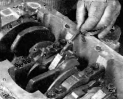
Fig. 10.3. Check the axial clearances in the connecting rods
4. Check the connecting rods and caps for identification markings (Fig. 10.4). If there are no clear markings, use a center punch to make the appropriate number of dots on each connecting rod and the corresponding cap (1, 2, 3, etc., depending on the cylinder they belong to).
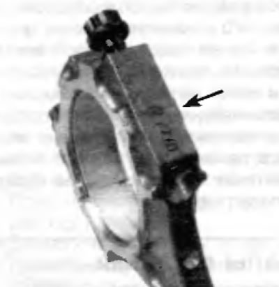
Fig. 10.4. If the connecting rods and connecting rod bearing caps are not marked, mark the bearing caps with the corresponding cylinder numbers. Do not confuse the markings shown here with the connecting rod numbers; this is the identification marking of the bearing size
5. Loosen each connecting rod bearing cap bolt ½ turn at a time until the bolts can be removed by hand. Remove connecting rod bearing cap #1 and the corresponding bearing shell. Do not remove the bearing shell from the cap.
6. Remove the bearing shell and lift the piston and connecting rod assembly out through the top of the engine. Use a wooden or plastic hammer handle to tap the seating surface for the upper bearing in the connecting rod.
7. If resistance is felt, check again whether the ridge in the cylinder has been completely removed.
8. Repeat the procedure on the remaining cylinders.
9. Once removed, assemble the connecting rod bearing caps and shells with the corresponding connecting rods, screw in the bolts and tighten them finger tight. Leaving the old bearing shells in place until assembly will help prevent accidental damage to the working surfaces in the connecting rods.
10. The pistons and connecting rods are now ready for inspection and repair, which should be carried out at a service station.
Installing piston rings
11. Before installing new piston rings, check the gaps in the ring joints. It is assumed that the piston ring gap in the groove has already been checked and found to be correct.
Note: Pistons and connecting rods can only be installed after the crankshaft has been installed (see paragraph 11).
12. Lay out the pistons and connecting rods and new ring sets so that when measuring the joint clearances and assembling the engine, the ring sets are matched to the same piston and cylinder
13. Insert the top (No. 1) ring into the first cylinder and position it perpendicular to the cylinder walls, pressing on it with the piston bottom (fig. 10.13). The ring should be located near the base of the cylinder, at the lower edge of the ring movement area.
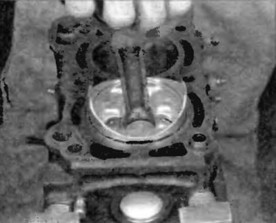
Fig. 10.13. Insert the top ring into the cylinder, and then use the piston to push it down to the standard depth so that the ring is not skewed in the cylinder
14. To measure the gap in the joint, insert a feeler gauge between the ends of the ring lock until you find a feeler gauge whose thickness is equal to the width of the gap (fig. 10.14). The feeler gauge should slide between the ends of the ring joint with little resistance. Consult your dealer for the correct joint gap for your specific engine. If the gap is greater or less than the specification, recheck to make sure you are using the correct type of rings before continuing.
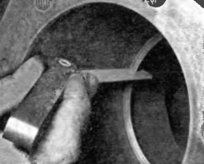
Fig. 10.14. With the ring positioned perpendicular to the cylinder walls, measure the gap in the ring lock with a feeler gauge
15. If the gap is too small, it should be increased, otherwise the ends of the ring lock may come into contact with each other when the engine is running, which may cause serious damage to the engine. The gap in the lock can be increased by very carefully filing the ends of the joint with a fine file. Clamp the file in a vice with soft jaws and slide the ring onto the file so that the ends of the ring contact the surface of the file. Then slowly move the ring to remove material from the ends. When doing this, move the ring only from the outer edge of the clamped file in the direction of the vice (fig. 10.15).
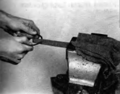
Fig. 10.15. If the gap in the ring lock is too small, clamp the file in a vice as shown and file the ends of the piston ring lock. Make sure that the ends are parallel and remove any unevenness and burrs with a file
18. Increased clearance in the lock is not critical if it does not exceed approximately 1 mm. Again, make sure that the correct type of ring is used.
17. Repeat the procedure for each ring that will be installed in cylinder #1 and for each ring in the remaining cylinders. Remember to maintain the alignment of the rings, pistons and cylinders.
18. After checking the ring gaps and making any necessary adjustments, the rings can be installed on the pistons.
Application: On V6 engines, pistons for the left bank of cylinders are marked with either an L or a single round mark on the front of the piston. Pistons for the first bank of cylinders are marked with either an R or two round marks on the front of the piston.
19. Usually the oil scraper ring is installed first (the lowest on the piston). It consists of three separate elements. Insert the expansion element into the groove (fig. 10.19, a). If there is a protrusion that prevents the ring from rotating, insert it into the hole drilled in the groove. Then install the top element of the ring in the same way (fig. 10.19, b). Do not use a piston ring installer on the end members of the oil control ring as they may be damaged. Instead, insert one end of the end member into the gap between the spacer/expander and the groove wall, hold it securely in place and run your finger around the perimeter of the piston, pushing the end member of the oil control ring into the groove. Finally, install the bottom member of the ring.
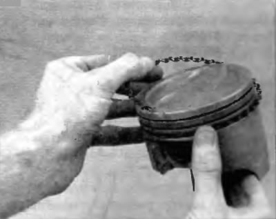
Fig. 10.19, a. Installing the spacer/expansion ring into the oil scraper ring groove
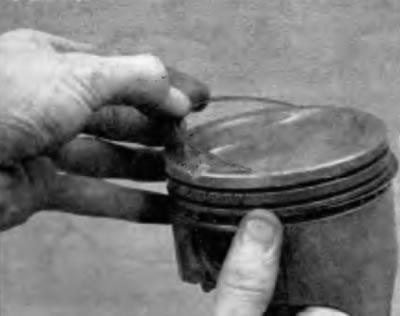
Fig. 10.19, b. Do not use a piston ring installer when installing the upper and lower elements of the oil scraper ring
20. After installing the three oil scraper ring elements, make sure that both the upper and lower ring elements can rotate freely and smoothly in their respective grooves.
(The original can be found on this resource: www.ToyotaMan.ru)
21. Next, install ring #2 (middle). It usually has a marking stamped on it that should face the piston bottom. Do not mix up the top and middle rings, as they have different cross-sections.
Note: Be sure to follow the instructions on the ring packaging. Different manufacturers may require different installation methods.
22. Use a piston ring installer and make sure the marking faces the piston bottom, then insert the ring into the middle groove on the piston (fig. 10.22). Do not open the ring more than is absolutely necessary to fit it onto the piston.
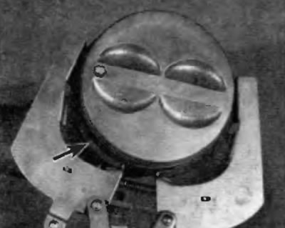
Fig. 10.22. Use a special tool to install piston rings No.2 into No.1 (upper). Make sure that the installation mark on the piston ring is facing the piston bottom
23. Install ring #1 (upper) in the same way. Make sure that the marking is facing up. Be careful not to mix up rings #1 and #2.
24. Repeat the procedure for the remaining pistons and rings.