
Numbering of outputs of switches with increased frequency of operation and with the mode of alternating cleaning and washing of glass
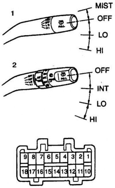
1. High frequency switch
2. Switch with the mode of alternating cleaning and washing the glass
Numbering of outputs of the rear window cleaner switch with increased frequency of operation and with the mode of alternating cleaning and washing the glass
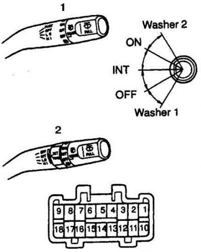
1. High speed rear window wiper switch
2. Rear wiper switch with alternating wipe and wash
Examination
1. Disconnect the battery from the ground.
2. Deactivate the airbag.
3. Remove the steering wheel.
4. Remove the steering column cover.
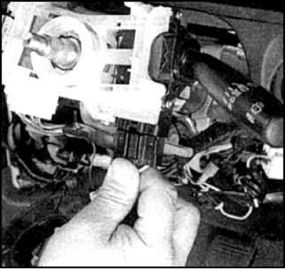
5. Disconnect the connector from the wiper switch.
6. Check for continuity between switch terminals (see fig. The numbering of the conclusions of the switches with increased frequency of operation and with the mode of alternating cleaning and washing the glass and fig. Numbering of outputs of the rear window cleaner switch with increased frequency of operation and with the mode of alternating cleaning and washing the glass).
High Frequency Switch (in fog)
7. In the OFF position of the switch, the circuit must be between terminals 7 and 16.
8. In the MIST switch position (fog) the circuit must be between terminals 7 and 17.
9. In switch position LO (weak move) the circuit must be between terminals 7 and 17.
10. In switch position HI (high speed) the circuit must be between terminals 8 and 17.
Switch with alternating glass cleaning and washer
11. In the OFF position of the switch, the circuit must be between terminals 7 and 16.
12. In the MIST switch position (fog) the circuit must be between terminals 7 and 16.
13. In switch position LO (weak move) the circuit must be between terminals 7 and 17.
14. In switch position HI (high speed) the circuit must be between terminals 8 and 17.
Rear window wiper switch
15. In switch position WASHER 1, the circuit must be between terminals 2 and 12.
16. In the OFF position of the switch, there should be no circuit between all terminals.
17. In the WIPER INT switch position, the circuit must be between pins 2 and 13.
18. In the WIPER ON switch position, the circuit must be between pins 2 and 10.
19. In switch position WASHER 2, the circuit must be between pins 2, 10 and 12.
20. To test both types of switches, make sure there is continuity between terminals 2 and 11 when the switch is in the ON position.
21. If the test results are negative, replace the switch.
Replacement
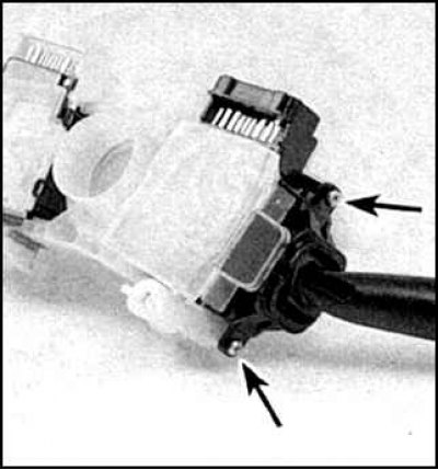
1. Remove the switch from the case. To do this, unscrew the two screws (indicated by arrows). The switch has been removed from the steering column.
2. Installation is carried out in the reverse order. Before installing the steering wheel, check the centering of the airbag wire coil (see subsection 9.14).