



Contents: Checking the rotor ↓ Stator check ↓ Checking the brushes ↓ Checking the rectifier unit ↓ Checking bearings ↓
Checking the rotor
1. Check if there is a break in the excitation winding.
Using an ohmmeter, measure the resistance between the slip rings.
Nominal resistance (in a cold state): 2.8-3.0 Ohm.
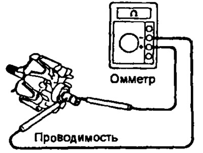
If the resistance tends to infinity, i.e. the circuit is open, then replace the rotor.
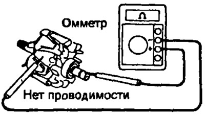
2. Check if the excitation winding is shorted to ground.
Using an ohmmeter, measure the resistance between the rotor pole and the slip ring. If there is no resistance (the circuit is closed), then replace the rotor.
3. Check the slip rings.
- a) Check the working surfaces of the contact rings. They should not have any burrs or chips.
- b) Using a caliper, measure the diameter of the slip rings.
- Nominal diameter: 14.2 -14.4 mm
- Minimum allowable: 12.8 mm
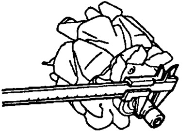
If the diameter of the slip rings is less than the minimum allowable, replace the rotor.
Stator check
1. Check if there is a break in the stator winding.
Using an ohmmeter, check for conductivity between the terminals of the stator winding coils.
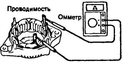
Otherwise, replace the stator.
2. Check if the stator winding is shorted to ground.
Using an ohmmeter, make sure there is no conductivity between the stator housing and the terminals of the stator winding coils.
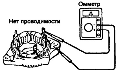
Otherwise, replace the stator.
Checking the brushes
1. Measure the length of the protruding part of the brushes.
- Nominal: 10.5 mm.
- Minimum allowable: 1.5 mm.
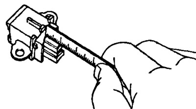
3S-FE, 4S-FE, 4A-FE and 7A-FE (type A), 5E-FE (models with manual transmission) | 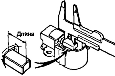
2S-T, 2S-T, 3S-GE, 4A-FE (type B), 5E-FE (models with automatic transmission) |
If the brush protrusion length is less than the minimum allowable length, replace the brushes (as a rule, models with manual transmission) or brush holder assembly (models with automatic transmission).
2. Replacing brushes (if necessary) a) Unsolder the brush wire from the brush holder terminal and remove the brush and brush spring.
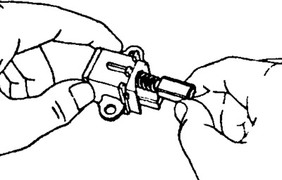
- b) Pass the wire through the hole in the brush holder and insert the brush into the brush holder.
- c) Solder the brush wire to the brush holder terminal so that the protruding length of the brush corresponds to the nominal value specified above.
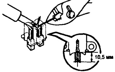
- d) Make sure that the brushes move freely without jamming.
- d) Cut off the remaining part of the wire.
- c) Apply insulating paint to the soldering points.
Checking the rectifier unit
1. Checking the positive valve.
- a) Connect the negative probe of the ohmmeter to the positive terminal of the rectifier block, and connect the positive probe in series to each of the other three terminals.
Make sure there is conductivity in all three measurements.
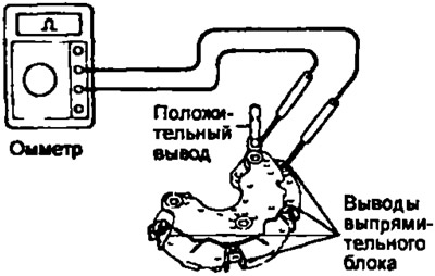
- b) Change the polarity of the tester probes and repeat the procedure of point a). Make sure there is no conductivity in all three measurements. If the conditions are not met, replace the rectifier unit.
2. Checking the negative valve.
- a) Connect the positive probe of the ohmmeter to the negative terminal of the rectifier unit, and connect the negative probe in series to each of the other three terminals. Check for continuity in all three measurements.
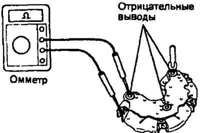
- b) Change the polarity of the tester probes and repeat the procedure in point a) Make sure there is no conductivity in all three measurements. If the conditions are not met, replace the rectifier unit.
Checking bearings
1. Check the front bearing. Check that the front bearing moves smoothly and without sticking.
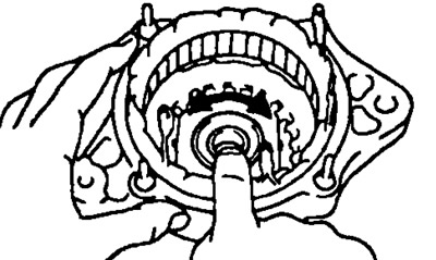
2. Replace the bearing if necessary.
- a) Unscrew 4 screws and remove the bearing holder.
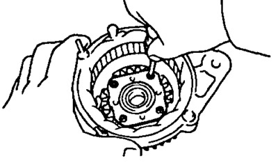
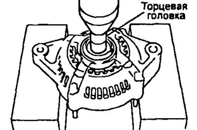
- b) Using a press and a socket head of the appropriate size, press out the front bearing.
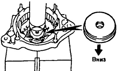
- c) Using a special punch and press, press the new front bearing into the generator cover on the drive side.
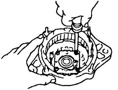
- d) Install the bearing holder and tighten the 4 screws that secure it.
3. Check the rear bearing. Check that the rear bearing moves smoothly and without sticking.
4. Replace the rear bearing if necessary.
- a) Using a puller, remove the outer bearing cover and rear bearing.
Note: Be careful not to damage the rotor.
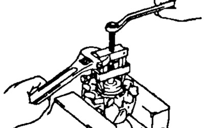
- b) Remove the inner bearing cover.
- c) Install the inner bearing cover onto the rotor.
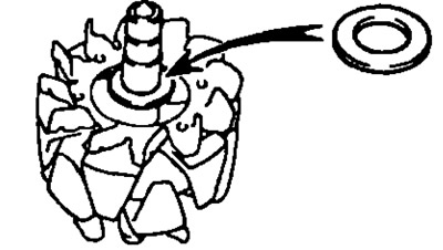
- b) Using a press and a mandrel, install the new rear bearing onto the rotor shaft.
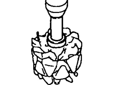
- c) Install the outer bearing cover.