Company Honda Company Ford Company Skoda Company Kia Company Mazda Company Mercedes Company Renault
English Русский
Български
Беларускі
Український
Српски
Hrvatski
Română
Polski
Slovenský
Magyar
Bookmark Articles Sitemap Contacts
ToyotaMan.ru


Camry Corolla Corona Carina Land Cruiser Highlander 4Runner RAV4 Others
Duet (1998-2004) Dyna Y50/Y60 (1984-1995)

Checking the elements of the electronic engine control system using an oscilloscope [Toyota Duet M100]

  • Main
  • Toyota
  • Duet (1998-2004)
  • Power unit
  • Fuel injection system
  • Checking the elements of the electronic engine control system using an oscilloscope
0
Contents: EJ-DE, EJ-VE ↓ KZ series ↓

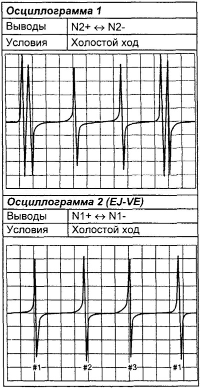
EJ-DE, EJ-VE


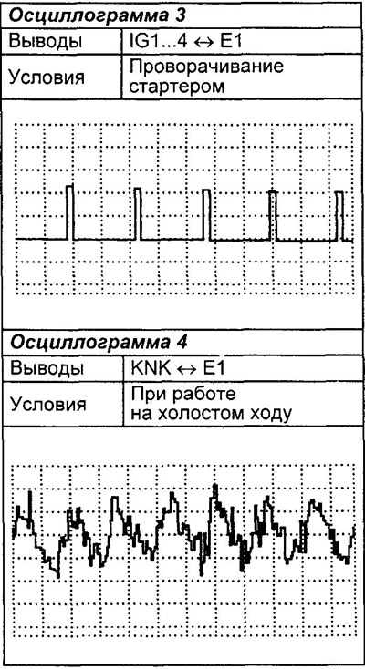
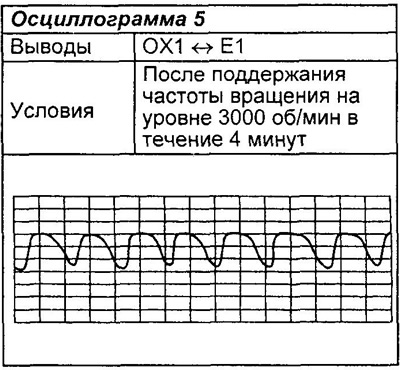
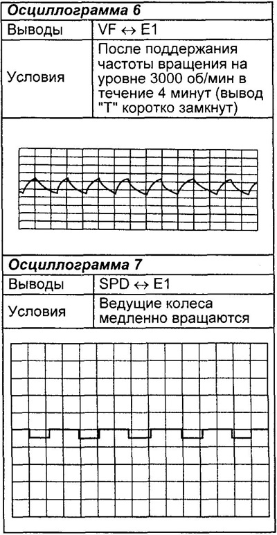
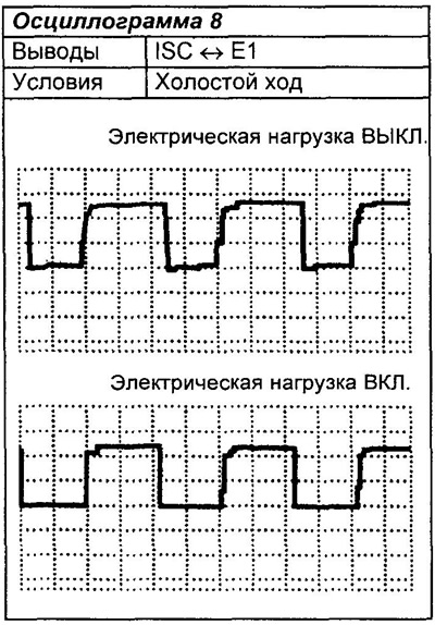
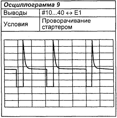
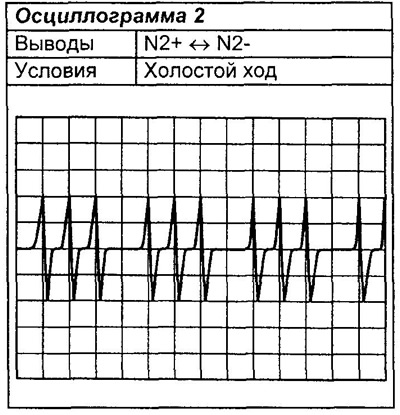
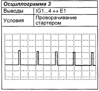
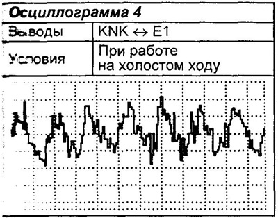
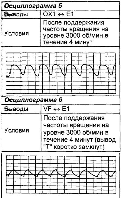
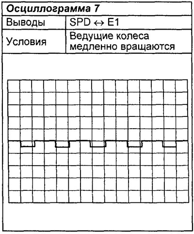
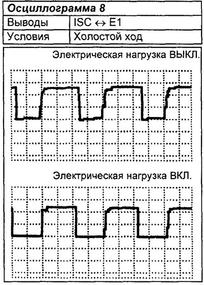
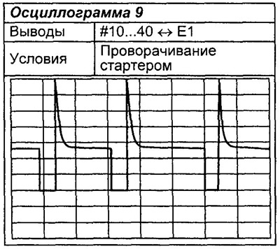
Note: The correct type of waveform is shown below.


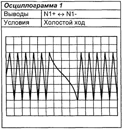
KZ series


Note: The correct type of waveform is shown below.


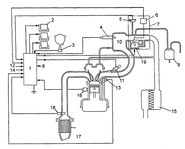
Schematic diagram of the electronic engine control system (EJ-DE).
1 - electronic control unit,
2 - ignition coil,
3 - crankshaft position sensor,
4 - intake air temperature sensor,
5 - absolute pressure sensor at the inlet,
6 - throttle position sensor,
7 - throttle body,
8 - start inhibit switch (models with automatic transmission),
9 - fuel vapor accumulator,
10 - upper part of the intake manifold,
11 - nozzle,
12 - diagnostic connector,
13 - coolant temperature sensor,
14 - vehicle speed sensor,
15 - air filter,
16 - knock sensor,
17 - catalytic converter,
18 - oxygen sensor,
19 - idle speed control system valve.
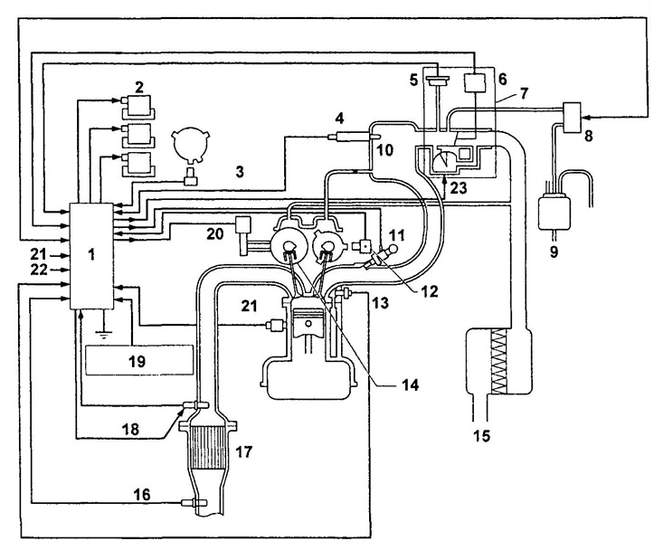


Schematic diagram of the electronic engine control system (EJ-VE).
1 - electronic control unit,
2 - ignition coil,
3 - crankshaft position sensor,
4 - intake air temperature sensor,
5 - absolute pressure sensor at the inlet,
6 - throttle position sensor,
7 - throttle body,
8 - electro-pneumatic valve,
9 - fuel vapor accumulator,
10 - upper part of the intake manifold,
11 - nozzle,
12 - camshaft position sensor,
13 - coolant temperature sensor,
14 - DWT system sprocket,
15 - air filter,
16 - rear oxygen sensor,
17 - catalytic converter,
18 - oxygen sensor (with heater),
19 - Start inhibit switch (models with automatic transmission),
20 - DVVT system valve,
21 - diagnostic connector,
22 - vehicle speed sensor,
23 - idle speed control system valve.
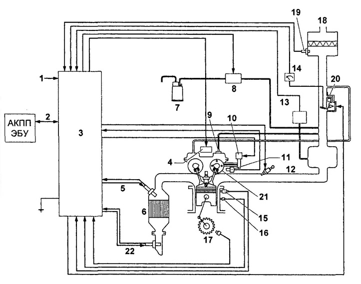


Electronic engine control system diagram (KZ-VE, K3-VE2).
1 - vehicle speed sensor,
2 - serial connection with the automatic transmission ECU,
3 - electronic control unit,
4 - ignition coil,
5 - oxygen sensor (with heater),
6 - catalytic converter,
7 - fuel vapor accumulator,
8 - electropneumatic valve,
9 - valve of the forced crankcase ventilation system,
10 - DWT system valve,
11 - camshaft position sensor,
12 - nozzle,
13 - absolute pressure sensor in the intake manifold,
14 - throttle position sensor,
15 - knock sensor,
16 - coolant temperature sensor,
17 - crankshaft position sensor,
18 - air filter,
19 - intake air temperature sensor,
20 - idle speed control system valve,
21 - WT system sprocket
22 - rear oxygen sensor (without heater).
This article is available at: russian, bulgarian, belarusian, ukrainian, serbian, croatian, romanian, polish, slovak, hungarian
The article material has been checked: Kolokoltsev Grigory
Share information:
◀ Previous
Duet: Fuel injection system
Next ▶

Checking signals at the terminals of the electronic control unit
Engine Management System Diagnostic Trouble Codes
Clear diagnostic code
Output of diagnostic codes
«Check Engine» indicator of diagnostic system
Precautions when working with the fuel system
Checking the fuel system on a car
Injectors — removal and installation
Fuel tank
Fuel pump
Similar articles on other Toyota models

➥ Checking the lighting control system elements Toyota Camry Vista V40 (1994-1998)
➥ Checking the ABS and PBS actuator (with the VSC stability… Toyota Corolla Verso 3 (2004-2009)
➥ Checking the automatic transmission and engine control unit Toyota Corona T190 (1992-1997)
➥ Checking the electro-pneumatic valve of the exhaust gas… Toyota Carina T190 (1992-1996)
➥ Using an oscilloscope to monitor the operating signals of a… Toyota Cruiser 100 (1998-2007)
➥ Emission Control and Engine Management System Specifications Toyota Highlander 1 (2000-2007, petrol)
Link in different formats to this article
Comments and feedback from visitors
No comments yet


Add two numbers 46 + 27


Duet (1998-2004) 
  • General information
  • User manual
  • Maintenance
  • Power unit
  • Petrol engines 1.0 l
  • Petrol engines 1.3 l
  • Engine overhaul
  • Cooling system
  • Lubrication system
  • Fuel injection system
  • Starting and charging system
  • Transmission
  • Clutch
  • Mechanical gearbox
  • Automatic gearbox
  • Drive shafts and cardan
  • Chassis, running gear
  • Car suspension
  • Steering
  • Brake system
  • Body and interior
  • Body elements
  • Heating and air conditioning
  • SRS security system
  • Electrical equipment
  • Equipment and devices
  • Electrical circuits
Dyna Y50/Y60 (1984-1995) 
  • Petrol engines «Y»
  • Checks and adjustments
  • Overhaul engine
  • Cooling and lubrication system
  • Fuel system
  • Starting and charging system
  • Ignition system
  • Diesel engines «L»
  • Engine repair
  • Cooling and lubrication system
  • Fuel system
  • Starting and charging system
  • Transmission
  • Clutch
  • Manual gearbox
  • Cardan shaft
  • Chassis, running gear
  • Car suspension
  • Brake system
  • Steering
  • Electrical equipment and body
  • Body elements
  • Equipment and devices
  • Electrical diagrams
ToyotaMan.ru © 2018–2026 • Mobile version • Interesting about Toyota • Administration • Sitemap: EN BG BY UA RS HR RO PL SK HU • Search system • Bookmark
Camry Vista-V40 • Camry XV10 • Camry XV20 • Camry XV30 • Corolla Verso-AR10 • Corolla E80 • Corona T190 • Carina T170 • Carina T190 • Land Cruiser J70 (diesel) • Land Cruiser J60 (petrol) • Land Cruiser J100 • Highlander XU20 (petrol) • 4Runner N120 • RAV4 XA10 • RAV4 XA20 • Duet M100 • Dyna Y50 •
We require cookies to enable some interactive features. Is that ok with you?