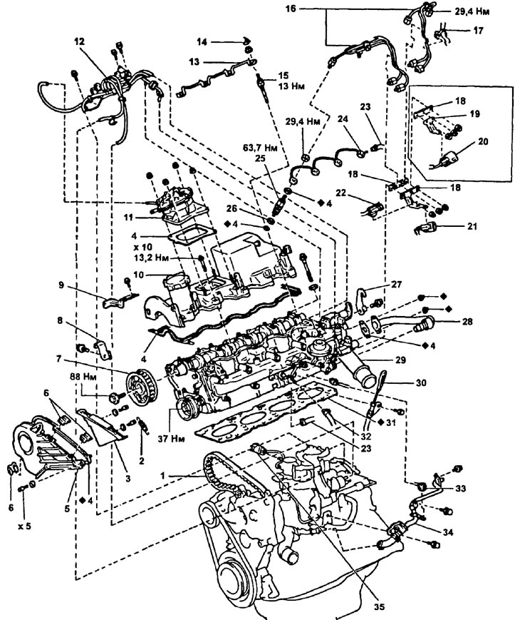
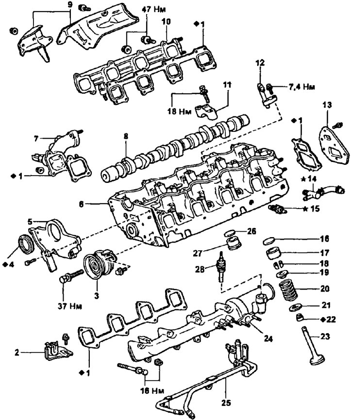
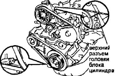
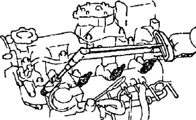
Details for removal and installation of a head of the block of cylinders (2S-T). 1 - timing belt; 2 - tension spring; 3 - cover No. 3 of the timing belt; 4 - gasket; 5 - cover No. 2 of the timing belt; 6 - clamp; 7 - a gear pulley of a camshaft; 8 - hook No. 1 for lifting the engine; 9—bracket clamp wiring harness; 10 - cylinder head cover; 11 - vacuum pump; 12 - electropneumatic valve and pressure sensor with hoses; 13 - connecting bus for glow plugs; 14 - insulating cap; 15 - glow plug; 16 - high pressure fuel pipe; 17 - collar (clamp) hose; 18 - clamp of high pressure fuel pipes; 19 - connector bracket; 20 - speed sensor connector and fuel cutoff solenoid valve; 21 - speed sensor connector; 22 - solenoid valve for cutting off the fuel supply; 23 - fuel outlet hose; 24 - fuel outlet pipe from the injectors; 25 - nozzle; 26 - nozzle seat; 27 - hook No. 2 for lifting the engine; 28 - pipeline of the exhaust gas recirculation system; 29 - outlet pipe of the cooling system; 30 - oil dipstick and guide assembly; 31 - cylinder head gasket; 32 - fuel supply hose; 33 - connector for the sensor of the coolant temperature indicator; 34 - coolant bypass tube; 35 - throttle position sensor connector.
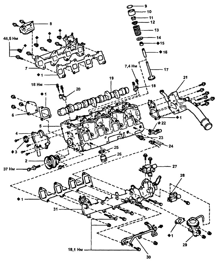
Parts for disassembly and assembly of the cylinder head (2S-T). 1 - gasket; 2 - tension roller; 3 - stuffing box; 4 - camshaft seal housing; 5 - cylinder head; 6 - cover of the coolant outlet pipe; 7 - exhaust manifold; 8 - heat shield of the exhaust manifold; 9 - adjusting washer; 10 - valve pusher; 11 - crackers; 12 - spring plate; 13 - valve spring; 14 - spring seat; 15 - oil scraper cap; 16 - valve guide sleeve; 17 - valve; 18 - oil nozzle; 19 - camshaft; 20 - camshaft bearing cover; 21 - coolant outlet pipe; 22 - fitting of the coolant bypass hose; 23 - coolant temperature indicator sensor; 24 - connector for the sensor of the coolant temperature indicator; 25 - adjusting washer; 26 - combustion chamber insert; 27 - vacuum control solenoid valve (EVRV) exhaust gas recirculation systems; 28 - electropneumatic valve of the exhaust gas recirculation system; 29 - valve of the exhaust gas recirculation system; 30 - fuel pipes; 31 - intake manifold.
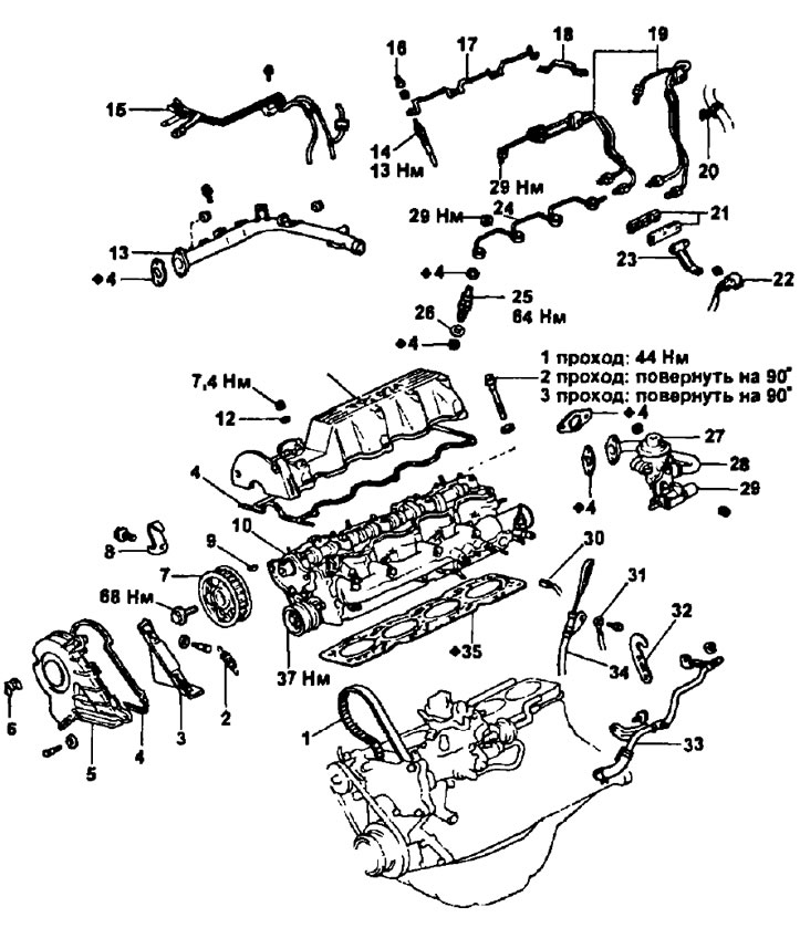
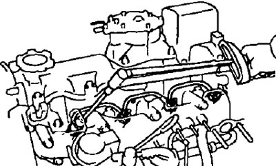
cylinder head (2C). 1 - timing belt; 2 - tension spring; 3 - cover No. 3 of the timing belt; 4 - gasket; 5 - cover No. 2 of the timing belt; 6 - clamp; 7 - a gear pulley of a camshaft; 8 - right hook for lifting the engine; 9 - key; 10 - cylinder head assembly; 11 - cylinder head cover; 12 - sealing washer; 13 - outlet pipe of the cooling system; 14 - glow plug; 15 - vacuum tube; 16 - insulating cap; 17 - connecting bus for glow plugs; 18 - current plate of the sensor; 19 - high pressure fuel pipe; 20 - collar (clamp) hose; 21 - clamp for high pressure fuel pipes; 22 - injection pump connector; 23 - connector bracket; 24 - fuel outlet pipe from the injectors; 25 - nozzle; 26 - nozzle seat; 27 - valve of the exhaust gas recirculation system; 28 - pipeline of the exhaust gas recirculation system; 29 - vacuum control solenoid valve; 30 - connector for the sensor of the coolant temperature indicator; 31 - ground wire; 32 - left hook for lifting the engine; 33 - heater tube; 34 - guide oil dipstick; 35 - cylinder head gasket.
Parts for disassembly and assembly of the cylinder head (2C). 1 - gasket; 2 - bracket for fastening the accelerator drive cable; 3 - tension roller; 4 - stuffing box; 5 - camshaft seal housing; 6 - cylinder head; 7 - coolant outlet pipe; 8 - camshaft; 9 - heat shield of the exhaust manifold; 10 - exhaust manifold; 11 - camshaft bearing cap; 12 - oil nozzle of the cylinder head; 13 - rear plate; 14 - fitting of the coolant bypass hose; 15 - coolant temperature indicator sensor; 16 - adjusting washer; 17 - pusher; 18 - cracker; 19 - upper thrust plate; 20 - valve spring; 21 - lower thrust plate; 22 - oil scraper cap; 23 - valve; 24 - intake manifold; 25 - fuel supply pipe; 26 - adjusting washer; 27 - combustion chamber insert; 28 - glow plug resistor.
Installing the cylinder head
Note:
- Thoroughly clean all parts to be installed.
- Lubricate all rotating and sliding surfaces with oil before installing parts.
- Replace all gaskets and seals with new ones.
1. (2S-T) Install the cylinder head oil jets by tightening the bolts.
- Tightening torque - 7.5 Nm
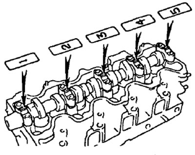
2. Install the camshafts. Install the five bearing caps in the correct sequence. Install and evenly tighten the camshaft bearing cap bolts in several passes.
Note: there are labels on the lids.
3. Check and adjust the valve clearance. (see section "Checking and adjusting thermal clearances in valves").
4. Install the camshaft oil seal housing.
5. (2S-T) Install a new gasket and tighten the coolant outlet cap with bolts.
- Tightening torque - 18 Nm
6 Install the check valve fitting on the cylinder head.
7. Install a new gasket and tighten the cooling system outlet pipe with bolts.
8. Install a new gasket and evenly tighten the exhaust manifold mounting bolts in several steps.
- Tightening torque - 47 Nm
9. Install the heat shield and tighten the two bolts.
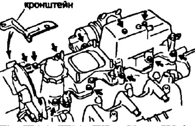
10. Install intake manifold and fuel pipe.
- A) Install a new gasket, intake manifold and fuel pipe.
- b) Evenly tighten the bolts and nuts securing the fuel pipe and intake manifold to the cylinder head.
- Tightening torque - 18 Nm
- V) Tighten the bolt securing the fuel pipe to the outlet pipe of the cooling system.
11. Pre-install the tension roller.
- Tightening torque - 7.5 Nm
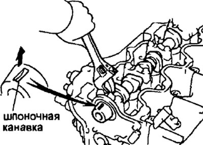
12. Set the piston of cylinder No. 1 to TDC of the compression stroke.
Note: set the piston of cylinder No. 1 to the TDC of the compression stroke to prevent the valves from hitting the piston crowns.
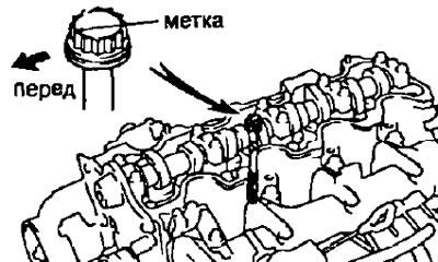
- A) Install the camshaft in a position where the keyway points up.
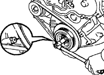
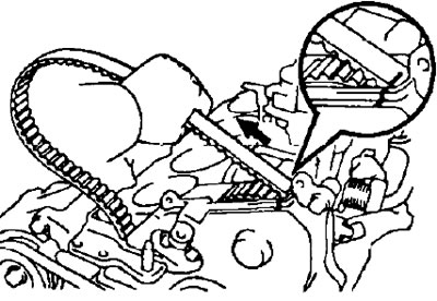
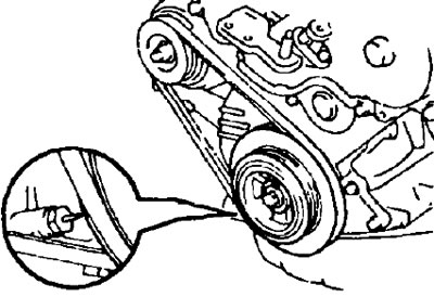
- 6) Align the alignment mark in the form of an arrow with the groove on the crankshaft pulley when turning the crankshaft pulley.
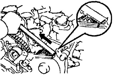
13. Check the position of the mounting mark on the timing belt. Check the alignment of the mounting marks on the timing belt and on the engine support bracket.
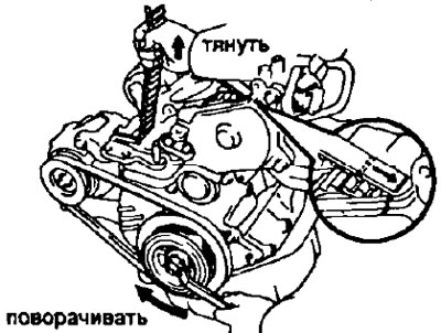
If the match marks are not aligned, align them as follows: Align the match marks by pulling the timing belt up to the oil pump pulley side while turning the crankshaft pulley clockwise.
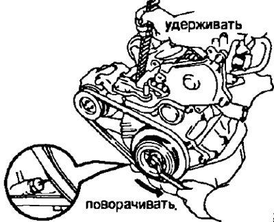
After aligning the alignment marks, while holding the timing belt, turn the crankshaft pulley counterclockwise and align its groove with the alignment mark in the form of an arrow.
14. Install the cylinder head.
- A. Install the cylinder head to the cylinder block.
- A) Lay a new cylinder head gasket on the cylinder block.
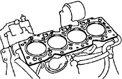
Note: Observe the correct position when installing the gasket.
- 6) Place the cylinder head on the cylinder head gasket.
- B. Install the cylinder head bolts.
Note:
- The cylinder head bolts are tightened in three consecutive steps.
- If any bolt is broken or deformed, replace it.
- A) Apply a light coat of engine oil to the threads and under the heads of the mounting bolts.
- b) Install plate washers under each cylinder head bolt.
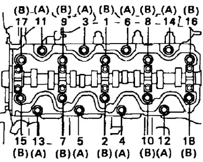
- V) Install and evenly tighten the 18 cylinder head bolts in several stages in the sequence shown in the figure.
- Tightening torque - 44 Nm
Note: bolt lengths "A" And "IN", are shown in the figure.
- "A" - 123 mm
- "IN" - 145 mm
If any of the bolts are out of specification, replace them.
- G) Mark the front of the cylinder head bolt head with paint.
- d) Tighten the cylinder head bolts 90°in the above sequence.
- e) Retighten the cylinder head bolts another 90°.
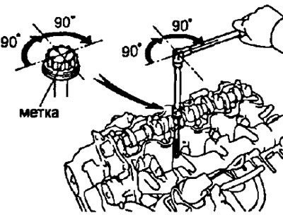
- and) Check that the colored label is now facing backwards, (180°from original position)
- h) (2S-T) Install the dipstick guide and secure it with the bolt.
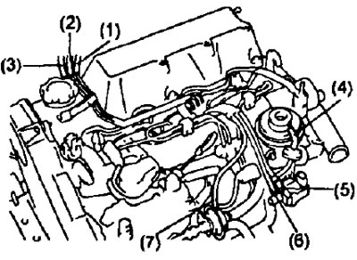
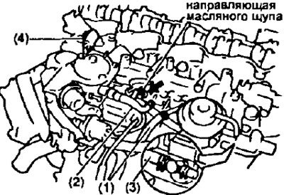
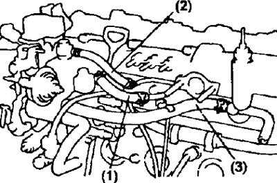
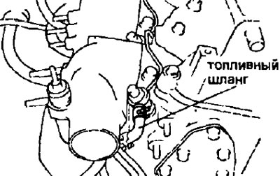
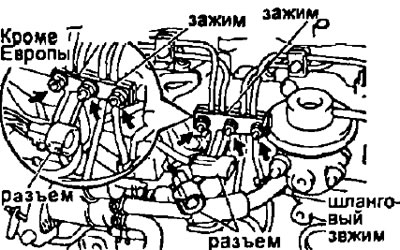
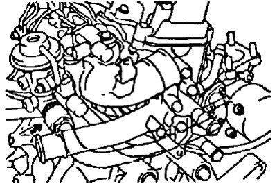
- And) Connect the following hoses:
- (1) - fuel supply hose to the fuel pipe;
- (2) - the fuel return hose to the fuel pipe;
- (3) - the coolant bypass hose to the fitting on the cylinder head;
- (4) - the control lever position sensor connector to the bracket.
2S-T.
2C
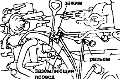
15. (2C) Install the dipstick guide, tighten the bolt and connect the wire "land".
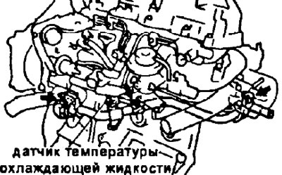
16.(2C) Connect the coolant temperature sensor connector.
17. Install the segment plug, after removing the old and applying new sealant material.
18. (2C) Install the right engine lifting hook by tightening the bolt.
- Tightening torque - 37 Nm
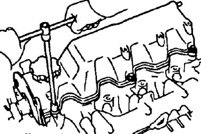
19. Establish a cover of a head of the block of cylinders.
- A) Remove the old sealant material.
- b) Apply sealant to the cylinder head at the locations shown in the illustration.
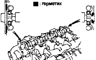
- V) Install the gasket on the cylinder head cover.
Note: If using an old gasket, lubricate the entire surface.
- G) Install the cylinder head cover and ten bolts. Tighten the bolts evenly in several steps.
- Tightening torque - 13 Nm
2S-T.
2C
- d) Install the harness clamp bracket by tightening the bolt.
20. Install the camshaft sprocket.
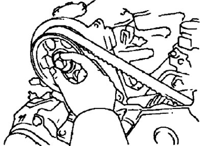
- A) Check that the keyway on the end of the camshaft is positioned as shown in the illustration.
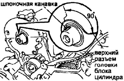
- b) Check that the groove on the camshaft pulley is aligned with the alignment mark in the form of an arrow.
- V) Check that the alignment marks on the timing belt and on the engine support bracket are aligned.
- G) Align the alignment marks on the timing belt and the injection pump sprocket by turning the sprocket.
- d) Install the key on the camshaft.
- e) Align the alignment marks on the timing belt and on the camshaft sprocket and slide the belt onto the sprocket.
- and) Install (slide in) toothed pulley on the camshaft.
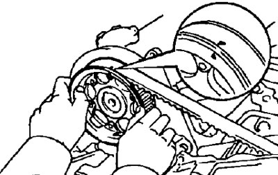
- h) Pre-tighten the camshaft sprocket bolt.
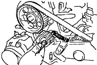
- And) Using a screwdriver, install the timing belt tension spring.
Note:
- Do not grasp the tension spring with pliers or the like.
- Loosen the idler bolt so that the idler can move slightly under the action of the tension spring.
- To) Slowly turn the crankshaft pulley two turns from TDC to TDC.
Note: Always turn the crankshaft clockwise.
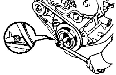
- l) Check that the timing marks on each pulley are aligned as shown.
If the timing marks are not aligned, remove the camshaft sprocket and reinstall it.
- m) Tighten the tension roller bolt.
- Tightening torque - 37 Nm
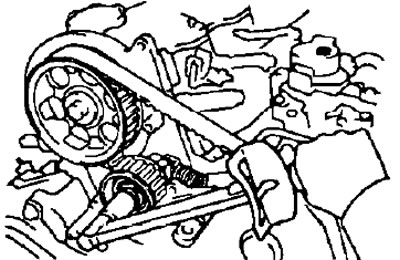
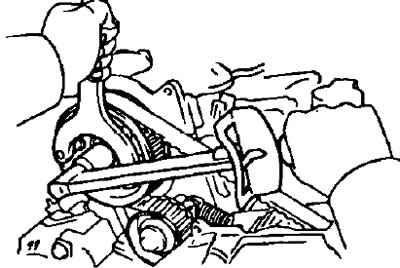
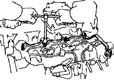
- n) Using the special tool, tighten the camshaft sprocket bolt.
- Tightening torque - 88 Nm
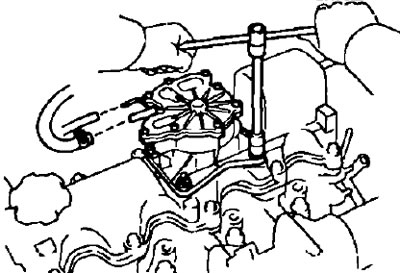
21. (2S-T) Install the vacuum pump.
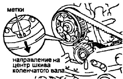
- A) Install the camshaft sprocket with the mark facing the center of the crankshaft sprocket.
- b) Install a new gasket on the cylinder head cover with the tab facing forward.
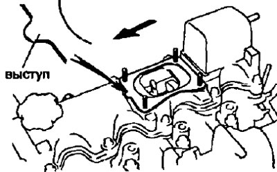
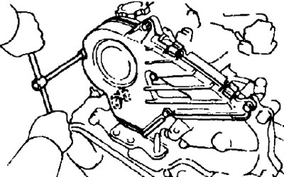
- V) Install the vacuum pump and four nuts. Tighten the nuts evenly in several steps.
- Tightening torque - 19 Nm
- G) Connect the vacuum hose from the tee to the vacuum pump.
- d) Connect the vacuum hose from the brake booster to the vacuum pump.
22. Install two sealing washers, timing belt cover #3 and tighten bolts.
23. Install timing belt cover #2.
- A) Install the gasket on the timing belt cover.
- b) Install the timing belt cover with five sealing washers, mounting bolts and three clips.
24. Install nozzles.
- A) Place four new gaskets and four new injector seats into the injector seats in the cylinder head.
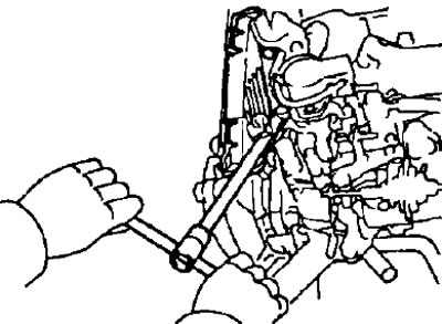
- 6) Using the special tool, install the four injectors.
- Tightening torque - 64 Nm
Note: Exceeding the specified tightening torque may cause deformation of the nozzle and sticking of the atomizer needle or other defects.
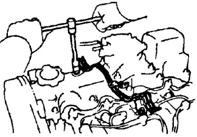
25. Establish a tube of removal of fuel from atomizers.
- A) Install four new gaskets and the fuel return pipe and secure it with four nuts.
- Tightening torque - 29 Nm
- b) Connect the fuel hose to the fuel outlet pipe.
26. Install high pressure fuel lines.
- A) Install the high pressure fuel pipe clamp to the intake manifold.
- b) Install four high pressure fuel lines.
- Tightening torque - 29 Nm
- V) Install the high pressure fuel line clamp and connector bracket with three nuts.
- G) (Some modifications) Install the two connectors on the high pressure fuel pipe clip (outer part).
- d) Install the connector on the bracket.
- e) Install the hose clamp to the coolant bypass hose.
27. Install glow plugs.
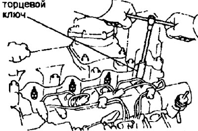
- A) Using a 12mm socket wrench, install the four glow plugs.
- Tightening torque - 13 Nm
- b) Install the amperage sensor plate and the glow plug connecting bar. Secure it with four nuts.
2S-T
28. Tighten the bolt and install the electro-pneumatic valve.
29. Tighten the two bolts and install the EGR pressure modulator.
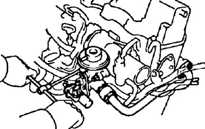
30. Install the EGR valve.
- A) Connect the vacuum hose to the electro-pneumatic valve of the exhaust gas recirculation system.
- b) Tighten the two nuts, install the gasket and the EGR valve.
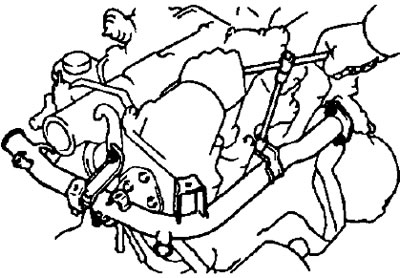
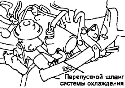
31. Install the bypass tube of the cooling system.
- A) Connect the coolant bypass hose to the fitting on the cylinder head.
- b) Install the coolant bypass pipe and tighten the three bolts.
- V) Install the coolant temperature sensor connector to the bracket.
32. (Some modifications) Install the EGR valve and pipe.
- A) Install a new gasket and tighten the EGR valve nuts and connect the vacuum hose to the EGR solenoid valve.
- Tightening torque - 18 Nm
- b) Install a new gasket and EGR pipe, tighten the two nuts and the flare nut.
- Torque:
- nuts - 18 Nm
- union nut - 74 Nm
33. Install the solenoid valve and pressure transducer by tightening the three bolts.
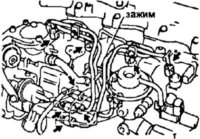
34. Connect the following vacuum hoses:
- (1) - hose to the vacuum pump;
- (2) - three hoses to high pressure fuel pump;
- (3) - two hoses to the pressure modulator (EVRV) exhaust gas recirculation systems;
- (4) - a vacuum hose to the electro-pneumatic valve of the exhaust gas recirculation system;
- (5) - the vacuum hose to the intake manifold.
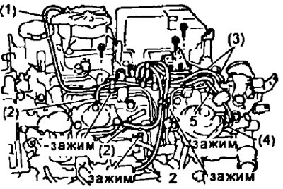
Install hose clamps to fuel pipes and hoses.
35. Install engine lifting hooks.
- Tightening torque - 37 Nm
36. Install the turbocharger (see section turbocharger). 2C
37. Install heater tube and left engine lifting hook.
- A) Disconnect the coolant bypass hose from the fitting on the cylinder head and remove the heater pipe and the left engine lifting hook.
- b) Tighten the bolt and nut.
38. Install the EGR pipe and valve.
- A) Install the valve, EGR pipe, two Gaskets and tighten the bolts.
- b) Tighten the union nut that secures the pipe to the exhaust gas recirculation valve.
39. Remove the outlet tube of the cooling system.
- A) Install the cooling system outlet pipe and tighten the three bolts.
- 6) Connect bypass hose (from the fitting on the cylinder head) to the outlet tube.
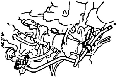
40. Install the vacuum tube.
- A) Install the vacuum tubes and tighten the three bolts.
- b) Connect the following hoses to the vacuum tubes:
- (1) - hose from the vacuum tube of the absolute pressure sensor (underpressure),
- (2) - hose from the vacuum tube (from the tee),
- (3) - hose from the vacuum tube (from the idle speed increase valve when the air conditioner is turned on),
- (4) - the hose from the exhaust gas recirculation valve,
- (5) - hose from the pressure modulator of the exhaust gas recirculation system (input channel),
- (6) - hose from the pressure modulator of the exhaust gas recirculation system (output channel),
- (7) - a hose from the drive of the system for increasing the idle speed when the air conditioner is turned on.