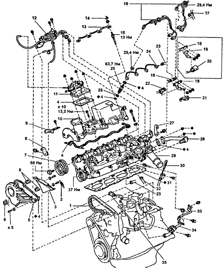
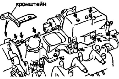
Details for removal and installation of a head of the block of cylinders (2S-T). 1 - timing belt; 2 - tension spring; 3 - cover No. 3 of the timing belt; 4 - gasket; 5 - cover No. 2 of the timing belt; 6 - clamp; 7 - a gear pulley of a camshaft; 8 - hook No. 1 for lifting the engine; 9 - bracket for clamping the wiring harness; 10 - cylinder head cover; 11 - vacuum pump; 12 - electropneumatic valve and pressure sensor with hoses; 13 - connecting bus for glow plugs; 14 - insulating cap; 15 - glow plug; 16 - high pressure fuel pipe; 17 - collar (clamp) hose; 18 - clamp of high pressure fuel pipes; 19 - connector bracket; 20 - speed sensor connector and fuel cutoff solenoid valve; 21 - speed sensor connector; 22 - solenoid valve for cutting off the fuel supply; 23 - fuel outlet hose; 24 - fuel outlet pipe from the injectors; 25 - nozzle; 26 - nozzle seat; 27 - hook No. 2 for lifting the engine; 28 - pipeline of the exhaust gas recirculation system; 29 - outlet pipe of the cooling system; 30 - oil dipstick and guide assembly; 31 - cylinder head gasket; 32 - fuel supply hose; 33 - connector for the sensor of the coolant temperature indicator; 34 - coolant bypass tube; 35 - throttle position sensor connector.
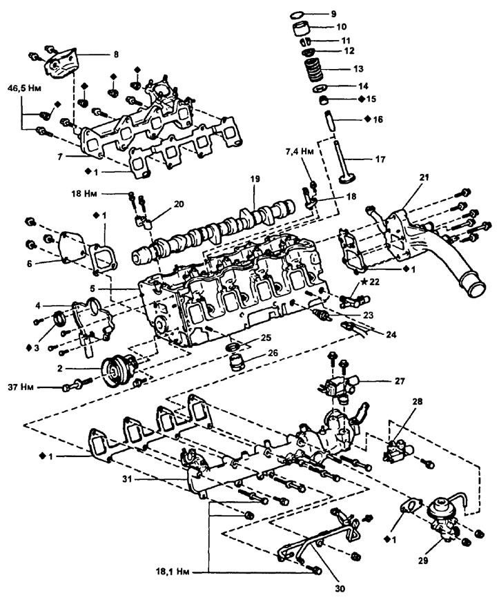
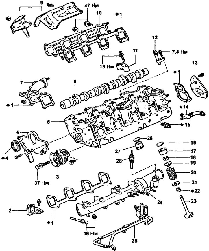
Parts for disassembly and assembly of the cylinder head (2S-T). 1 - gasket; 2 - tension roller; 3 - stuffing box; 4 - camshaft seal housing; 5 - cylinder head; 6 - cover of the coolant outlet pipe; 7 - exhaust manifold; 8 - heat shield of the exhaust manifold; 9 - adjusting washer; 10 - valve pusher; 11 - crackers; 12 - spring plate; 13 - valve spring; 14 - spring seat; 15 - oil scraper cap; 16 - valve guide sleeve; 17 - valve; 18 - oil nozzle; 19 - camshaft; 20 - camshaft bearing cover; 21 - coolant outlet pipe; 22 - fitting of the coolant bypass hose; 23 - coolant temperature indicator sensor; 24 - connector for the sensor of the coolant temperature indicator; 25 - adjusting washer; 26 - combustion chamber insert; 27 - vacuum control solenoid valve (EVRV) exhaust gas recirculation systems; 28 - electropneumatic valve of the exhaust gas recirculation system; 29 - valve of the exhaust gas recirculation system; 30 - fuel pipes; 31 - intake manifold.
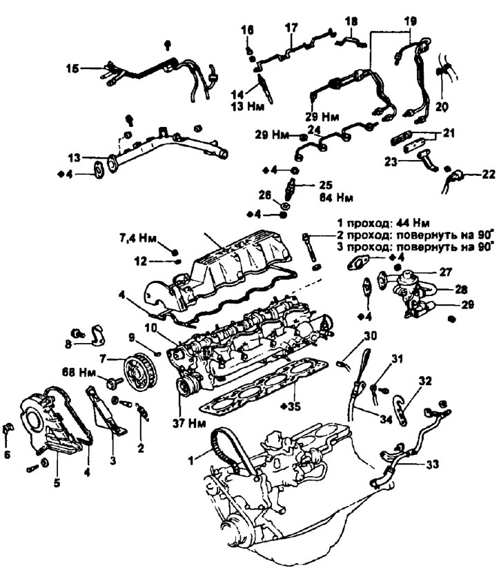
cylinder head (2C). 1 - timing belt; 2 - tension spring; 3 - cover No. 3 of the timing belt; 4 - gasket; 5 - cover No. 2 of the timing belt; 6 - clamp; 7 - a gear pulley of a camshaft; 8 - right hook for lifting the engine; 9 - key; 10 - cylinder head assembly; 11 - cylinder head cover; 12 - sealing washer; 13 - outlet pipe of the cooling system; 14 - glow plug; 15 - vacuum tube; 16 - insulating cap; 17 - connecting bus for glow plugs; 18 - current plate of the sensor; 19 - high pressure fuel pipe; 20 - collar (clamp) hose; 21 - clamp for high pressure fuel pipes; 22 - injection pump connector; 23 - connector bracket; 24 - fuel outlet pipe from the injectors; 25 - nozzle; 26 - nozzle seat; 27 - valve of the exhaust gas recirculation system; 28 - pipeline of the exhaust gas recirculation system; 29 - vacuum control solenoid valve; 30 - connector for the sensor of the coolant temperature indicator; 31 - ground wire; 32 - left hook for lifting the engine; 33 - heater tube; 34 - guide oil dipstick; 35 - cylinder head gasket.
Parts for disassembly and assembly of the cylinder head (2C). 1 - gasket; 2 - bracket for fastening the accelerator drive cable; 3 - tension roller; 4 - stuffing box; 5 - camshaft seal housing; 6 - cylinder head; 7 - coolant outlet pipe; 8 - camshaft; 9 - heat shield of the exhaust manifold; 10 - exhaust manifold; 11 - camshaft bearing cap; 12 - oil nozzle of the cylinder head; 13 - rear plate; 14 - fitting of the coolant bypass hose; 15 - coolant temperature indicator sensor; 16 - adjusting washer; 17 - pusher; 18 - cracker; 19 - upper thrust plate; 20 - valve spring; 21 - lower thrust plate; 22 - oil scraper cap; 23 - valve; 24 - intake manifold; 25 - fuel supply pipe; 26 - adjusting washer; 27 - combustion chamber insert; 28 - glow plug resistor.
Removing the cylinder head
2S-T
1. Remove the turbocharger.
2. Remove engine lifting hooks.
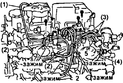
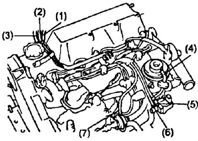
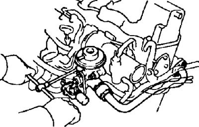
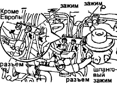
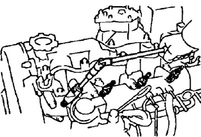
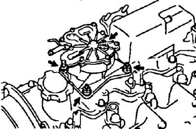
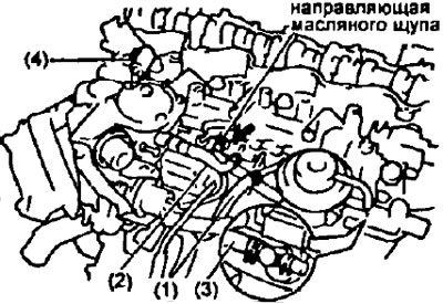
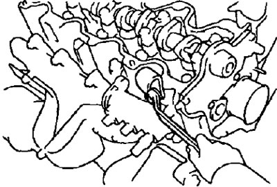
3. Disconnect the hose clamps shown in the illustration from the high pressure fuel pipes and hoses. Disconnect the following vacuum hoses:
- (1) - hose from the vacuum pump;
- (2) - three hoses from high pressure fuel pump;
- (3) - two hoses from the pressure modulator (EVRV) exhaust gas recirculation systems;
- (4) - vacuum hose from the electro-pneumatic valve of the exhaust gas recirculation system;
- (5) - the vacuum hose from the intake manifold.
4. (Models for Europe) Remove the pipe and EGR valve.
- A) Loosen the union nut on the EGR valve.
- b) Loosen the two nuts, remove the EGR pipe and gasket.
- V) Disconnect the vacuum hose, remove the two nuts and remove the EGR valve.
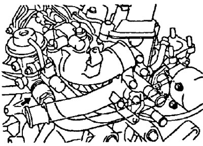
5. Remove the bypass tube of the cooling system.
- A) Disconnect the coolant temperature gauge sensor connector from the coolant bypass hose bracket.
- b) Remove three bolts.
- V) Disconnect the bypass pipe of the cooling system from the fitting on the cylinder head and remove the heater pipe.
6. Remove the EGR valve.
- A) Disconnect the vacuum hose from the electro-pneumatic valve of the exhaust gas recirculation system.
- b) Unscrew the two nuts, remove the EGR valve and the gasket.
7. Turn away two bolts and remove the modulator of pressure of system recirculation OG.
8. Turn away a bolt and remove the electropneumatic valve.
2C
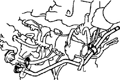
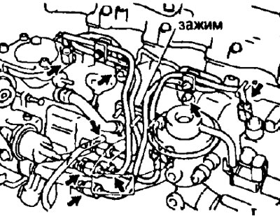
1. Remove the vacuum tubes.
- A) Disconnect the following hoses from the vacuum tubes:
- (1) - hose from the vacuum tube of the absolute pressure sensor (underpressure),
- (2) - hose from the vacuum tube (from the tee),
- (3) - hose from the vacuum tube (from the idle speed increase valve when the air conditioner is turned on),
- (4) - the hose from the exhaust gas recirculation valve,
- (5) - hose from the pressure modulator of the exhaust gas recirculation system (input channel),
- (6) - hose from the pressure modulator of the exhaust gas recirculation system (output channel),
- (7) - a hose from the drive of the system for increasing the idle speed when the air conditioner is turned on.
- b) Turn away three bolts and remove vacuum tubes.
2. Remove the outlet tube of the cooling system.
- A) (Some modifications) Disconnect the bypass hose (from the fitting on the cylinder head) from a profitable tube.
- b) Turn away three bolts and remove an output tube of system of cooling.
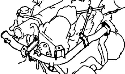
3. Remove the pipe and the EGR valve.
- A) Loosen the union nut that secures the pipe to the exhaust gas recirculation valve.
- 6) Loosen the bolts and remove the valve, EGR pipe and two gaskets.
4. Remove heater tube and left engine lifting hook.
- A) Loosen the bolt and nut
- b) Disconnect the cooling system bypass hose from the fitting on the cylinder head and remove the heater pipe and the left engine lifting hook.
All engines
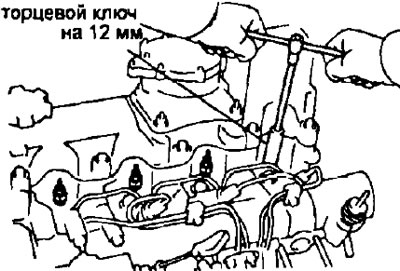
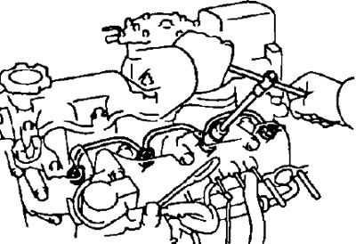
1. Remove the glow plugs.
- A) Remove the four rubber caps.
- b) Turn away four nuts, remove the connecting tire of glow plugs.
- V) Using a 12mm socket wrench, remove the four glow plugs.
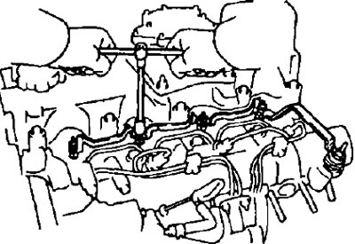
2. Remove the high pressure fuel pipes.
- A) Disconnect the two connectors from the high pressure fuel line clamps (outer part).
- b) Disconnect the connector from the bracket.
- V) After unscrewing the three nuts, remove the connector bracket and the clamp of the high pressure fuel pipes (outer part).
- V) Disconnect the hose clamp from the high pressure fuel pipe.
- G) Loosen the eight union nuts and remove the four high pressure fuel pipes and the inner part of the clamp.
3. Remove the fuel outlet pipe from the injectors.
- A) Disconnect the fuel hose from the fuel outlet tube.
- b) Turn away four nuts, remove a tube of removal of fuel and four linings.
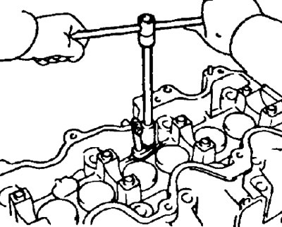
4. Remove nozzles.
Using a special tool. remove the four injectors, remove the injector seats and gaskets.
Note: Arrange the nozzles in the correct order.
5. Remove timing belt cover #2.
- A) Remove three clamps.
- b) After unscrewing the five bolts, remove the sealing washers, timing belt cover and gasket.
6. Remove timing belt cover #3.
After unscrewing the two bolts, remove the sealing washers and the timing belt cover.
7. (2S-T) Remove the vacuum pump
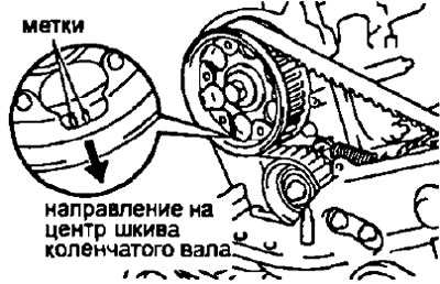
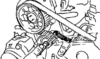
- A) Rotate the crankshaft pulley and install the camshaft sprocket with the mark towards the center of the crankshaft pulley.
- 6) Loosen the four nuts and remove the vacuum pump and gasket.
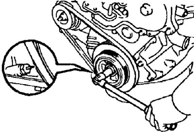
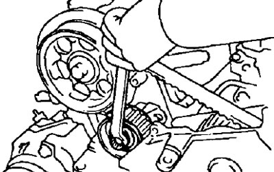
8. Remove a gear pulley of a camshaft.
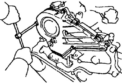
- A. Using the special tool, loosen the camshaft sprocket bolt.
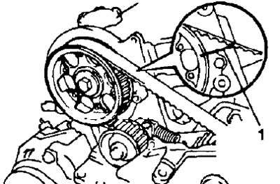
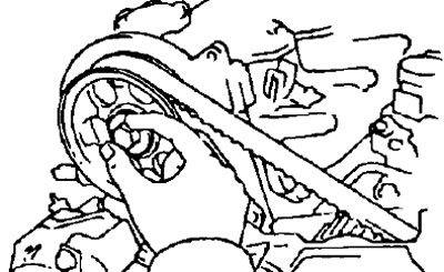
- B. Set the piston of cylinder No. 1 to TDC of the compression stroke.
- A) Rotate the crankshaft pulley and align the timing mark arrow with the groove on the crankshaft pulley.
- 6) Check that the timing mark on the camshaft sprocket is aligned with the top slot of the cylinder head plane. If not, turn the crankshaft pulley one turn (360°)
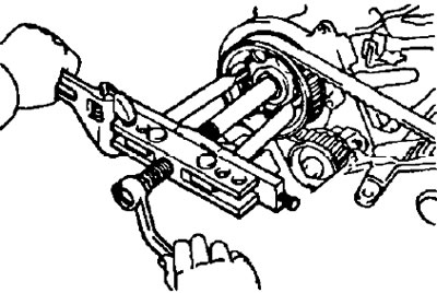
- B. Remove the camshaft sprocket.
- A) Mark the timing belt, camshaft and injection pump sprocket, and right engine support bracket.
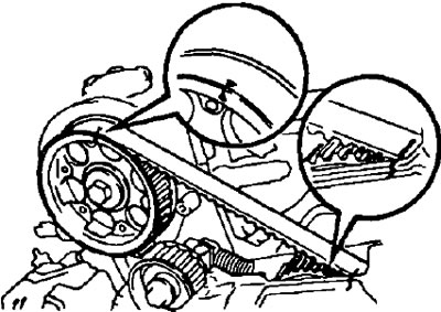
- 6) Using a screwdriver, remove the belt tension spring.
Warning: Do not use pliers or similar tool to grip the spring.
- V) Loosen the tension roller bolt.
- G) Remove the camshaft sprocket bolt.
- d) Using a puller, remove the camshaft sprocket along with the timing belt.
- e) Remove the key from the camshaft.
Note:
- Be careful not to drop anything inside the timing belt cover.
- Keep the belt away from oil, water or dust.
- and) Turn away a bolt of a tension roller and remove a roller.
- h) Turn away bolts of a tension roller and remove it.
9. Remove the cylinder head cover.
- A) Loosen the bolt and remove the wire harness clamp bracket.
- V) After unscrewing the bolts, remove the cylinder head cover and gasket.
2S-T
2C
10. Remove the segment plug.
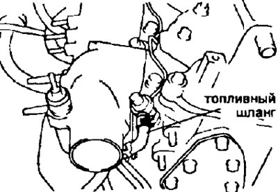
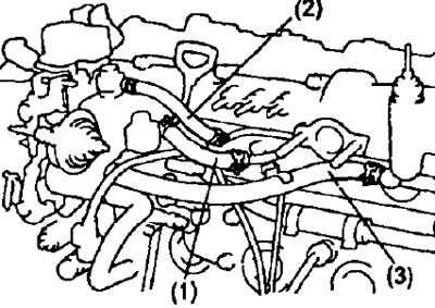
11. Disconnect the following hoses and remove the oil dipstick guide.
- A) Disconnect the following hoses and connections:
- (1) - fuel supply hose from the fuel pipe;
- (2) - fuel return hose from the fuel pipe;
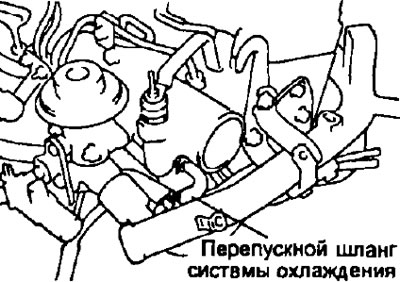
- (3) - the coolant bypass hose from the fitting on the cylinder head;
- (4) - the control lever position sensor connector from the bracket.
2S-T
2C
- b) Remove the bolt and disconnect the dipstick guide from the intake manifold.
12. (2C) Loosen the bolt and remove the right engine lifting hook.
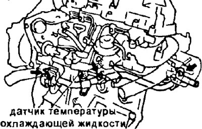
13. Disconnect a socket of the gauge of temperature of a cooling liquid and remove the gauge.
14. Remove the cylinder head.
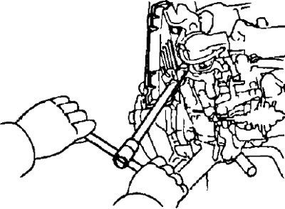
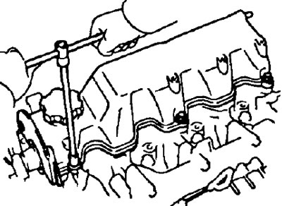
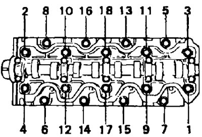
- A) Gradually unscrew the 18 cylinder head bolts in several stages in the sequence shown in the figure.
Warning: Warping or cracking of the cylinder head may occur if the bolts are removed in the correct order.
- b) Remove 18 plate washers.
- V) Lift the cylinder head off the guide pins on the cylinder block and place the wooden blocks on the workbench.
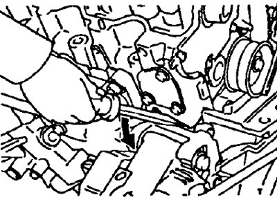
Note:
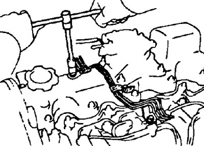
- If there is difficulty in lifting the cylinder head, use a lever between the coolant outlet pipe and the alternator bracket.
- Be careful not to damage the adjacent planes of the cylinder head and cylinder block.
15. Having turned away bolts and nuts, remove a fuel pipe, an inlet collector and a lining.
16. Remove the exhaust manifold.
- A) Loosen the two bolts and remove the exhaust manifold heat shield.
- b) After unscrewing the bolts and nuts, remove the exhaust manifold and gasket.
17. Having turned away bolts, remove an output branch pipe of system of cooling and a lining.
18. Remove fitting (on the cylinder head) (bypass hose) coolant.
19. (2S-T) Loosen the bolts and remove the coolant outlet cap.
20. Having unscrewed bolts, remove the case of an oil epiploon of a camshaft.
21. Remove the camshaft by unscrewing the bots.
- A) Slowly loosen and remove the bearing cap bolts in sequence.
- b) Remove bearing caps.
Note: Check the labels on the caps or apply your own labels if necessary to ensure proper installation sequence.
22. (2S-T) Loosen the bolt and remove the oil nozzles.
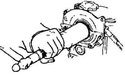
Replacing the camshaft seals
Note: There are two ways to replace the oil seal, depending on whether the camshaft oil seal housing is removed or not.
1. If the camshaft oil seal housing is removed from the cylinder head.
- A) Using a screwdriver and hammer, remove the seal.
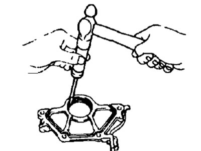
- b) Lubricate the seal with grease.
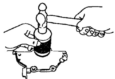
- V) Using a mandrel (tube of suitable diameter) and a hammer, press the new oil seal into the housing flush with the edge of the housing.
2. If the camshaft oil seal housing is not removed from the cylinder head.
- A) Using a knife, cut the lip of the seal as shown in the illustration.
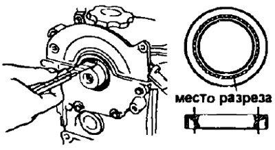
- 6) Using a screwdriver, remove the seal from the cover.
Note: Wrap the end of the screwdriver with electrical tape and be careful when removing the oil seal so as not to damage the camshaft.
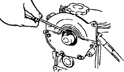
- V) Lubricate the seal with grease.
- G) Using a frame (or a tube of suitable diameter) and a hammer, press the oil seal into the seat of the camshaft oil seal housing.