Note: checking and adjusting the thermal clearances in the valves is carried out on a cold engine.
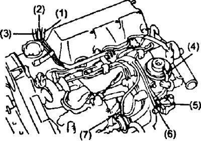
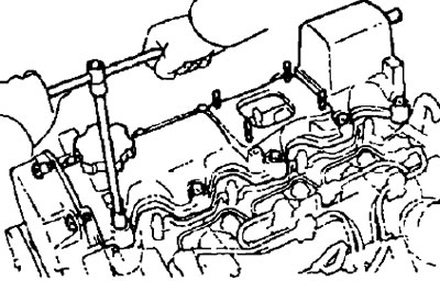
1. (2C) Remove the vacuum tube.
- A) Disconnect the following hoses from the vacuum tube:
- (1) - hose from the vacuum tube of the absolute pressure sensor (underpressure),
- (2) - hose from the vacuum tube (from the tee),
- (3) - hose from the vacuum tube (from the idle speed increase valve when the air conditioner is turned on),
- (4) - the hose from the exhaust gas recirculation valve,
- (5) - hose from the pressure modulator of the exhaust gas recirculation system (input channel),
- (6) - hose from the pressure modulator of the exhaust gas recirculation system (output channel),
- (7) - a hose from the drive of the system for increasing the idle speed when the air conditioner is turned on.
- b) Turn away three bolts and remove a vacuum tube.
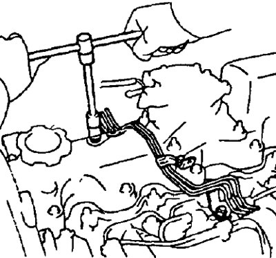
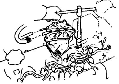
2. Remove the vacuum pump
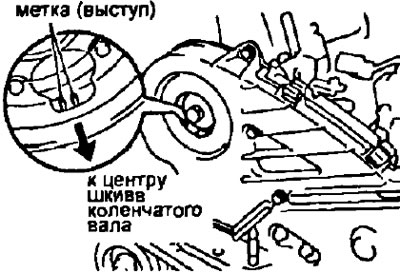
- A) Install the camshaft pulley with the mark facing the center of the crankshaft pulley.
- b) Disconnect the vacuum hoses from the vacuum tube.
- V) After unscrewing the nuts, remove the vacuum pump and gasket.
3. Turn away bolts and remove a cover of a head of the block of cylinders and a lining.
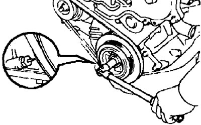
4. Set the piston of cylinder No. 1 to TDC of the compression stroke.
- A) Turn the crankshaft pulley clockwise until its groove is aligned with the injection advance indicator.
- b) Check that the valve lifters for cylinder #1 are loose and the valve lifters for cylinder #4 are tight. If not, turn the crankshaft one turn (360°) and align the match marks as described above.
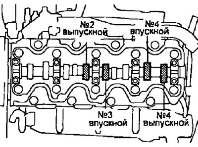
5. Check up a backlash in valves.
- A) Check only the clearances shown in the figure. Using a feeler gauge, measure the clearance between the valve lifter and camshaft.
Write down the measurement results. These will later be used to determine the required thickness of the new shim
- valve clearances (measured on a cold engine):
- intake valve - 0.20-0.30 mm
- exhaust valve - 0.25-0.35 mm
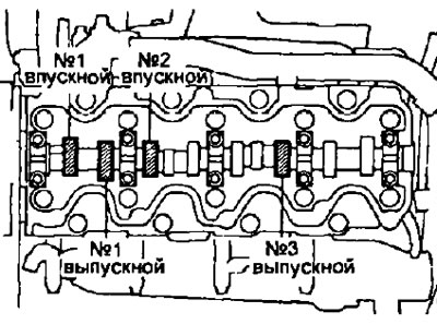
- b) Rotate the crankshaft pulley one turn (360°) until its groove is aligned with the injection advance angle indicator.
- V) Check only those valves shown in the figure.
6. Adjust valve clearances.
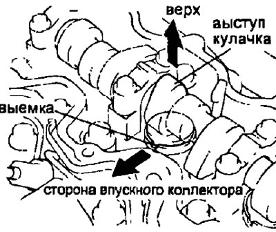
- A) Remove the adjusting washer. Rotate the crankshaft so that the camshaft lobe is pointing up.
Position the notch in the valve lifter so that it faces the intake manifold.
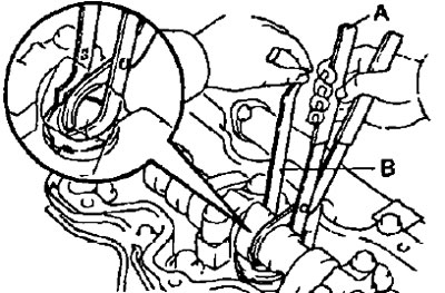
- b) Using a special tool (A), press down on the valve lifter and install the special tool (IN) between the camshaft and the valve lifter.
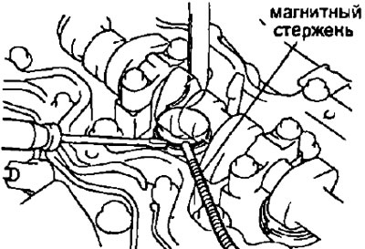
- V) Using a small screwdriver and a magnetic bar, remove the old shim.
- G) Measure the thickness of the removed shim with a micrometer. Calculate the thickness of the new shim so that the calculated gap satisfies the values given in the specifications:
- T - thickness of the removed washer, mm
- A - measured gap, mm
- N is the thickness of the new washer, mm
- Inlet valve - N \u003d T + [A-0.25 mm]
- Exhaust valve - N=T+[A-0.30mm]
Pick up an adjusting washer with a thickness closest to the calculated one.
Note: Shims come in 25 sizes, from 2.20mm to 3.40mm in 0.05mm increments. The thickness is stamped on the washer.
- d) Install a new shim in the valve lifter.
- e) Using a special tool (A), push down on the valve lifter and remove the tool (IN).
Check the valve clearance again.
7. Install the cylinder head cover.
8. Install the vacuum pump.
9. Install the vacuum tube.
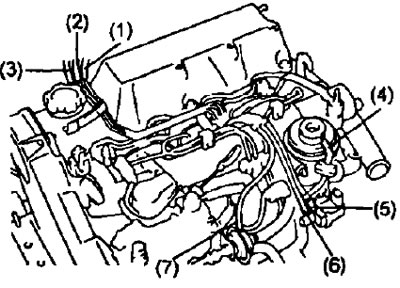
10. (2C) Connect the following hoses to the vacuum tube:
- (1) - hose from the vacuum tube of the absolute pressure sensor (underpressure),
- (2) - hose from the vacuum tube (from the tee),
- (3) - hose from the vacuum tube (from the idle speed increase valve when the air conditioner is turned on),
- (4) - the hose from the exhaust gas recirculation valve,
- (5) - hose from the pressure modulator of the exhaust gas recirculation system (input channel),
- (6) - hose from the pressure modulator of the exhaust gas recirculation system (output channel),
- (7) - a hose from the drive of the system for increasing the idle speed when the air conditioner is turned on.