
Checking the ignition coil
Note: terms "cold'' and "hotter" state indicate the temperature of the windings:
- "cold" — from -10°C to -50°C
- "hot" — from +50°C to +100°C
These definitions are retained in the future also in relation to the inductive coils of the angular momentum sensors.
1. Check the resistance of the primary winding using an ohmmeter by connecting it to the ignition coil as shown in the figures.
- V "cold" state - 0.36-0.55 Ohm
- V "hot" condition - 0.45-0.65 Ohm
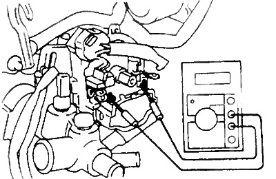
Models with TRC
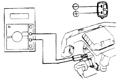
Models without TRC
2. Check the resistance of the secondary winding using an ohmmeter by connecting it to the ignition coil as shown in the figures.
Rated resistance:
- V "cold" state 9.0-15.4 kOhm
- V "hot" state - 11.4-18.1 kOhm
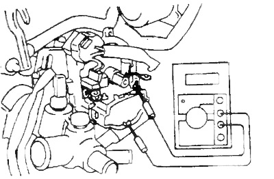
Models with TRC
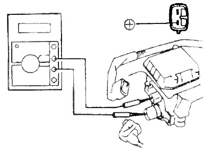
Models without TRC
If the resistance of any of the ignition coil windings is not within specification, replace the ignition coil.
Distributor check
Disconnect the distributor connector, remove the distributor cap and ignition distributor rotor.
1. Using a feeler gauge, check the air gap between the teeth of the rotor of the angular impulse sensors and the protrusion of the core of the inductive coil of this sensor.
Note: Several angle pulse sensors can be used in the ignition system (crankshaft angle sensor NE and camshaft angle sensors G, G1, G2), then similar measurements should be performed for each sensor.
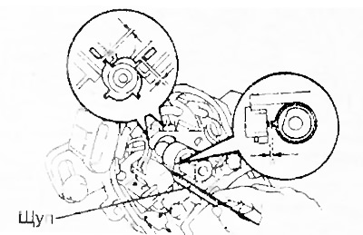
Models with TRC
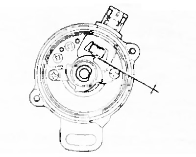
Models without TRC
- Nominal air gap - 0.2 - 0.4 mm
If the clearance is out of specification, replace the distributor housing assembly.
2. Using an ohmmeter, check the electrical resistance of the inductive coils of the crankshaft and camshaft angle pulse sensors. The ohmmeter connection diagrams are shown in the figures, and the pin numbers to which the ohmmeter must be connected, and the nominal values of the resistances of the inductive coils of the angular pulse sensors are given in the table. The value of the electrical resistance of the inductive coils of the sensors of angular impulses.
IN "cold" condition:
with TRC:
- G (+) and G (-) - 185 -275 Ohm
- NE (+) and NE (-) - 370-550 Ohm
without TRC:
- NE (+) and NE (-) — 135 - 210 Ohm
IN "hot" condition:
with TRC:
- G (+) and G (-) - 240 -325 Ohm
- NE (+) and NE (-) — 475 - 650 Ohm
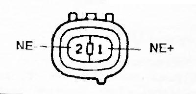
Models without TRC
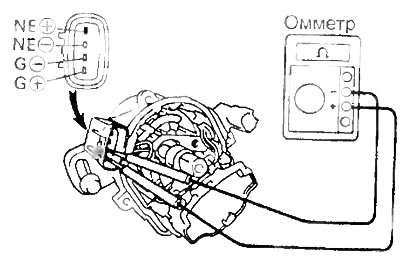
Models with TRC
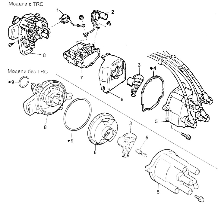
Distributor
1 - capacitor,
2 - wiring connector,
3 - rotor,
4 - gasket,
5 - cover and high-voltage wires,
6 - anther of the ignition coil,
7 - ignition coil,
8 - distributor housing,
9 - ring seal.