
Check for "spark"
Check for spark (Contact ignition system):
A) Disconnect the high voltage wire from the distributor.
b) Holding the wire about 12.5mm away from the car body ("masses"), turn on the starter.
V) When cranking the engine, a spark should jump.
If no spark appears, test as described below. (Contactless ignition system)
A) Disconnect the high voltage wires from the spark plugs.
b) Remove spark plugs.
V) Connect the high voltage wires to the spark plugs.
G) Ground spark plugs.
d) Check up presence of a neoplasm when cranking the engine with a starter.
If there is no sparking, test as described in Table 1.
Checking high voltage wires
1. Carefully remove the high voltage wires from the spark plugs by holding the rubber end of the wire.
Attention: when disconnecting the wire, pull on the ferrule and not on the wire itself.
Measure the resistance of each wire.
- Maximum resistance - 25 kOhm
Attention: pulling or bending the wires can damage the conductor inside.
2. Without removing the high-voltage wire from the distributor, measure its resistance with an ohmmeter.
- Maximum resistance: 25 kOhm.
If the resistance is higher than the specified value, check the conclusions. If necessary, replace the wire or distributor cap.
 |  |
Checking spark plugs (with conventional electrodes)
Spark gap size:
- standard candle - 0.8 mm
platinum candle:
- nominal - 1.1 mm
- maximum allowable - 1.3 mm
1. Turn out spark plugs.
2. Clean the spark plugs with a cleaner or a metal brush.
3. Check the spark plugs visually for EDM wear on the electrodes, damaged threads and insulator. If any defects are found, replace the spark plugs.
4. Adjust the gaps between the electrodes of the spark plugs. Gap: 0.8mm.
5. Install spark plugs.
- Tightening torque - 18 Nm
Checking spark plugs (with platinum electrodes)
Attention:
- Do not use a wire brush to clean spark plugs;
- Do not attempt to adjust the gap between the electrodes at the working (in operation) candles;
- Spark plugs should be replaced every 100,000 km.
1. Check the electrodes:
A) Using a megohmmeter (insulation resistance meter), check the insulation resistance, the value of which should be more than 10 MΩ. If the resistance is less, replace the spark plug.
b) In the absence of a megohmmeter, it is necessary to quickly accelerate the engine to 4000 min-1 5 times. Then stop the engine, turn out the candles and visually assess their condition:
- if the electrodes are dry, then everything is in order,
- if the electrodes are wet, clean the spark plug.
2. Turn out spark plugs.
3. Visually inspect the condition of the spark plugs for damage to the insulator and threads. If defects are found, replace the spark plug.
- Spark plug brands: ND P16R
4. Check the gap between the electrodes.
- Maximum clearance - 1.3 mm
If the gap is larger, replace the spark plug.
- Nominal gap on a new candle - 1.1 mm
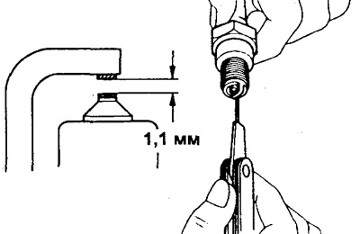
When adjusting the gap on a new spark plug, bend the side electrode at its base without touching the electrode.
5. Clean spark plugs with gasoline and spark plug cleaner.
- Air pressure - up to 6 kg / cm2 (588 kPa)
- Cleaning duration - up to 20 s
6. Install spark plugs.
- Tightening torque - 18 Nm
Checking the ignition coil (contact ignition system)
1. Disconnect the high voltage wire.
2. Using an ohmmeter, check the resistance of the primary winding at the terminals (+) And (-).
- Primary resistance (cold) should be within: 1.3-1.6 ohms
Otherwise, replace the ignition coil.
3. Check the resistance of the secondary winding by connecting with an ohmmeter to the terminal (+) and high voltage output. Secondary winding resistance (cold) should be in the range of 10.7-14.5 kOhm. Otherwise, replace the ignition coil.
4. Check the resistance of the additional resistor (installed on the ignition coil). The resistance value should be in the range of 1.3-1.5 ohms. Otherwise, replace the resistor.
5. Check the insulation resistance between the positive terminal of the ignition coil and the ignition coil housing with an ohmmeter. The resistance should be equal to infinity.
6. Check the power line.
A) With the ignition on, use a voltmeter to check for voltage at the output of the additional resistor by turning on the positive (+) voltmeter output to resistor terminal (black and red wire), and the negative (-) voltmeter output to ground. (-). The voltage should be around 12V.
b) After starting the engine with a voltmeter, check for voltage between the terminal (+) ignition coils and ground (-). The voltage should be around 12V.
If there is a problem, check the ignition switch and wiring harness.
Table 1.
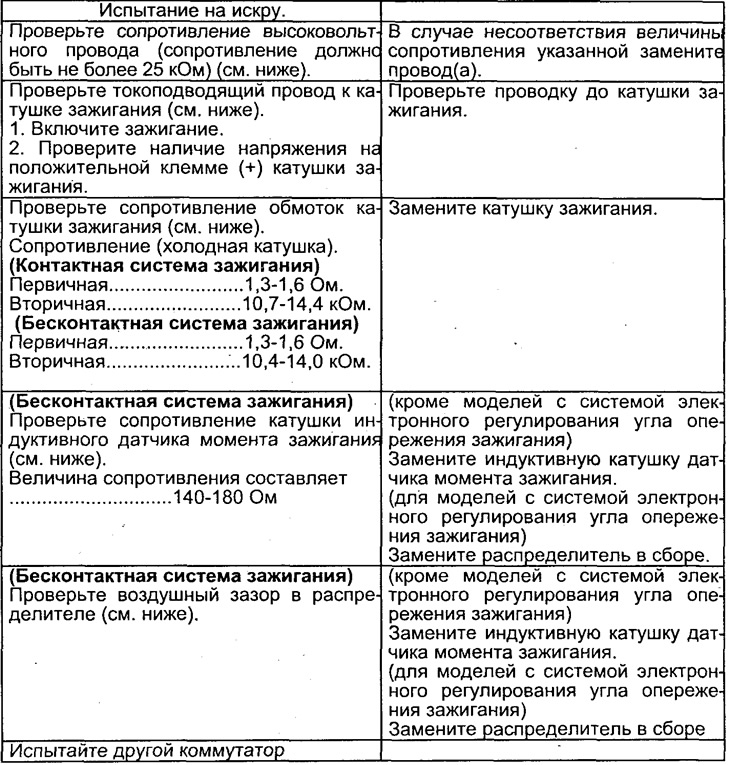
Table 2.
Checking the ignition coil (electronic ignition system)
1. Remove the distributor cap, distributor rotor and dust deflector.
2. Check the resistance of the primary winding of the ignition coil at the terminals (+) And (-).
- The value of the resistance of the primary winding (cold): 1.3-1.6 ohm
3. Check the resistance of the secondary winding between the terminal (+) and high voltage terminal.
- The value of the resistance of the secondary winding (cold): 10.4-14.0 kΩ
If the resistance value of the primary or secondary windings of the ignition coil is outside the specified limits, replace the ignition coil.
Checking the Switch (electronic ignition system)
(See spark plug test procedure).
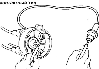
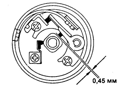
Distributor check (contact ignition system)
1. Check the contact group by measuring the gap between the cam and the plastic pusher with a feeler gauge. The gap should be about 0.45 mm. Adjust if necessary.
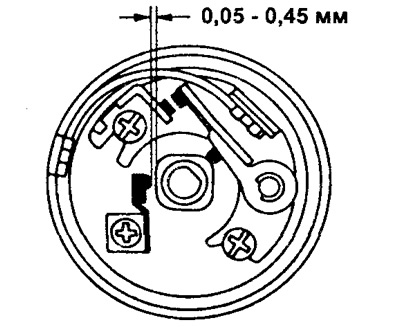
2. Check the damping spring by measuring the gap between the cam and the damping spring with a feeler gauge. The gap should be within 0.05-0.45 mm.
If the gap is outside this range, adjust it.
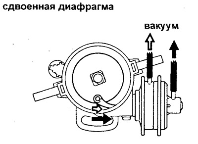
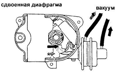
3. Check up a vacuum regulator of an advancing of ignition.
A) Disconnect the vacuum (s) handset (And) distributor and connect it (their) to vacuum (nym) pump (am).
b) Apply a vacuum and check that the vacuum regulator is free to move. If the vacuum regulator does not work, repair or replace it.
4. Check up a centrifugal regulator of an advancing of ignition.
A) Turn the rotor clockwise and make sure the rotor quickly returns to its original position counterclockwise.
b) The rotor must have a tight (no backlash) fit on the drive shaft.
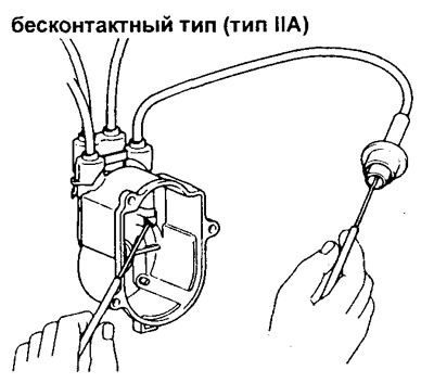
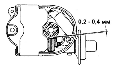
Distributor check (non-contact ignition system)
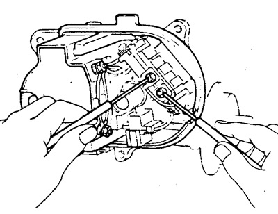
1. Use a feeler gauge to check the air gap between the rotor of the ignition timing sensor and the inductive coil of this sensor. The gap should be within 0.2-0.4 mm. If the clearance is out of specification, replace the torque sensor assembly.
2. Check the induction coil of the ignition timing sensor with an ohmmeter, as shown in the figure. Coil resistance: 140-180 ohm. Otherwise, replace the ignition timing sensor coil.
3. Check up a vacuum regulator of an advancing angle of ignition.
A) Disconnect the vacuum (e) hose (And) distributor and connect it (their) to vacuum (nym) pump (am).
b) Create a vacuum and check the mobility of the vacuum regulator.
If the vacuum regulator does not work, replace the regulator.
4. Check up a centrifugal regulator of an advancing angle of ignition.
A) Turn the rotor clockwise, release it and check that the rotor quickly returns to its original position counterclockwise.
b) The rotor must have a tight (no backlash) landing on the drive shaft.