



Contents: 1992 and 1993 models ↓ 1994 and 1995 models ↓
Location of electrical components and sensors of the engine fuel system
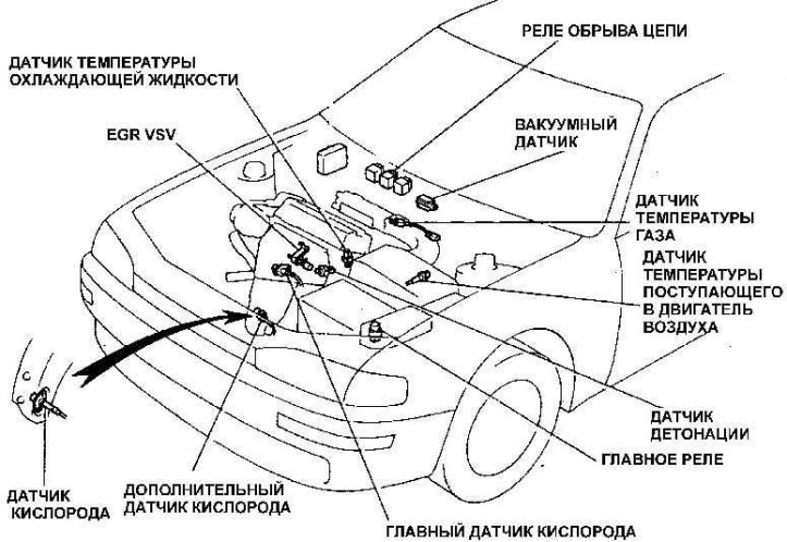
Location of the circuit breaker relay
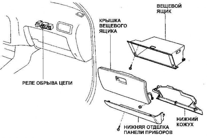
There are two relays in the fuel pump control circuit - the EFI main relay and the open circuit relay.
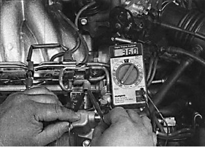
1. Remove the EFI main relay, turn the ignition on and check for battery voltage reaching the relay connector terminals.
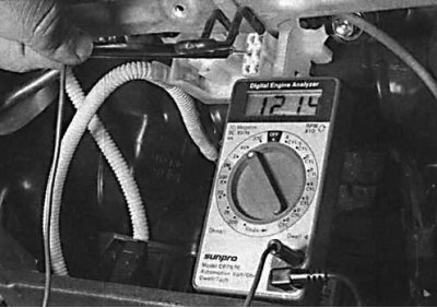
2. If battery voltage is present at the main relay connector terminals, install the relay and check for battery voltage being supplied to the open circuit relay.
3. If voltage is supplied to the connector contacts, check the relay.
1992 and 1993 models
EFI Main Relays
1. Using an ohmmeter, check that the resistance between pins 1 and 3 is minimal and that the resistance between pins 2 and 4 is infinite.
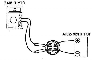
2. Using additional wires, connect contacts 1 and 3 to the battery. The resistance between contacts 2 and 4 should be 0.
Open circuit relay (four-cylinder engines)
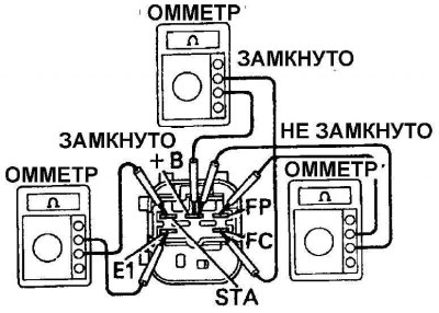
1. Using an ohmmeter, check that the resistance between the STA and E1 terminals and the +B and FC terminals is 0, and that the resistance between the +B and FP terminals is infinity.
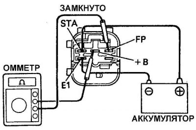
2. Using additional wires, connect the battery to the SPA and E1 contacts. The resistance between the +B and FP contacts should be 0.
Open circuit relay for six-cylinder engines
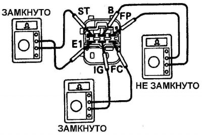
1. Using an ohmmeter, check the resistance of the open circuit relay between terminals ST and E1 and terminals ID and IC, which should be 0. The resistance between terminals B and FR should be infinity.
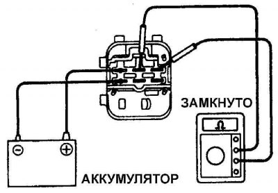
2. Using additional wires, connect the battery to the contacts of the ST and E1 open circuit relay. The resistance between the +B and FP contacts should be 0.
1994 and 1995 models
Main relay (Nippodenso)
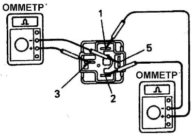
1. Using an ohmmeter, check that the resistance between pins 1 and 2 is 0 and between pins 3 and 5 is infinity.
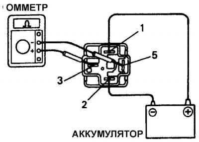
2. Using additional wires, connect the battery to contacts 1 and 2. The resistance between contacts 3 and 5 should be 0.
EFI Main Relay (BOCSH)
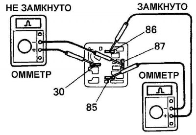
1. Using an ohmmeter, check that the resistance between pins 86 and 85 is 0 and that the resistance between pins 87 and 30 is infinity.
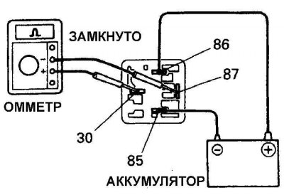
2. Using additional wires, connect the battery to contacts 85 and 86. The resistance between contacts 87 and 30 should be 0.
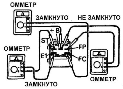
3. Using an ohmmeter, check that the resistance between the TS and E1 terminals and the +B and FC terminals is 0, and that the resistance between the +B and FP terminals is infinity.
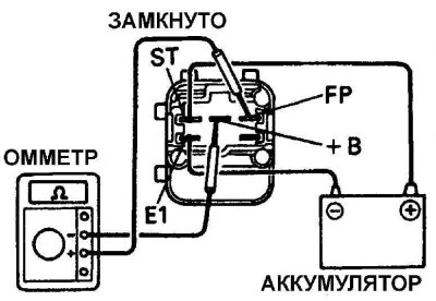
4. Using additional wires, connect the battery to contacts FT and E1. The resistance between contacts +B and FT should be 0.