
2. Before attempting to troubleshoot an electrical circuit, first study the relevant circuit diagram. You must have a complete understanding of the nature of the elements that make up a particular problem circuit. The list of possible causes of a malfunction can be narrowed down if you identify elements of this circuit that work correctly. If more than one element or circuit is failing at the same time, the problem is likely with a common fuse or ground at the «mass».
3. Electrical faults are usually the result of simple causes such as poor contact or corroded connections/connectors, a blown fuse or fuse, or a faulty relay. Before checking the elements, visually inspect the condition of all fuses, wires and connections in the problem circuit.
4. In the case of using diagnostic tools for troubleshooting, carefully plan, in accordance with the attached electrical diagrams, at which points in the circuit and in what sequence the tool should be connected in order to most effectively identify the cause of the malfunction.
5. The main tools needed for troubleshooting electrical circuits include a tester or voltmeter (you can also use a 12 volt test/test light with lead set to perform some tests); electrical continuity tester (control lamp with self-powered supply and a set of appropriate wires); changeover connecting wire (preferably with built-in circuit breaker or fuse), which can be used to bypass electrical elements (Pic. 2.5, a, b). Before attempting to solve a problem with test equipment, determine from the wiring diagram where the instrument should be connected.
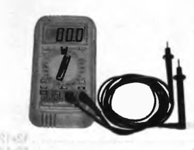
Pic. 2.5, a. The most useful tool for troubleshooting electrical equipment is a digital multimeter that can measure voltage, current, and resistance in an electrical circuit (turn on continuity check)
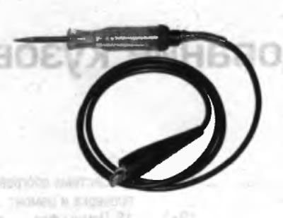
Pic. 2.5, b. A very convenient device for checking the presence of voltage is a simple test lamp
Voltage test
6. Voltage checks should be performed in the event of an electrical circuit failure. Connect one tester lead to the negative battery terminal or to a known good point «masses». Connect the other wire to a connector on the circuit under test, preferably as close to the battery or fuse as possible (pic. 2.6). Run the indicator on the tester is on, voltage is present, which means that the section of the circuit between the corresponding connector and the switch is working. Continue to check the rest of the chain in the same way. When is reached «dot», the voltage in which is absent, which means that the cause of the malfunction must lie between this «dot» and the previous test «dot», in which the voltage was recorded. Most problems are caused by a loose connection.
Note. Be aware that some electrical circuits are only energized when the ignition key is turned «ACC» (Accessories) or «RUN» (Job).
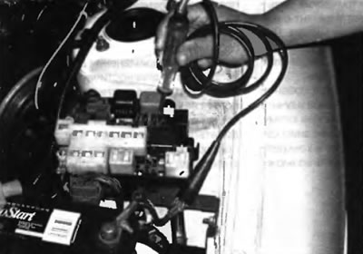
Pic. 2.6. When using a test lamp on the main wire is fixed with a clamp at a known good point «masses», and then using a pointed probe, you can check the electrical connectors by tracing their contacts. If the lamp is on, battery voltage is present in the circuit under test
Short circuit test
7. One method for finding a short circuit is to remove the appropriate fuse from the circuit and connect a test lamp (you should make two connecting wires with small spade terminals, connect these wires to the fuse box and connect a test lamp). There must be voltage in the electrical circuit. Pull the wiring while watching the pump. If the lamp starts flashing, there is a short circuit somewhere in this harness to «mass», possibly caused by chafing of the wire insulation.
Grounding check
8. This test is performed to determine the reliability of the earthing of the element. Disconnect the battery and connect one of the tester or multimeter wires (configured to measure resistance) to a known good point «masses». The other wire should be connected to the wire or point being tested «masses». If the resistance is low (less than 5 ohm), grounding is normal. If the indicator on the tester lights up, the ground connection is faulty.
Checking the integrity of the electrical circuit
9. The test is performed in order to detect breaks in the electrical circuit, i.e. to find out if the current is flowing correctly. After turning off power to this circuit, test it with a self-powered tester or multimeter. Connect the instrument wires to both ends of the electrical circuit (or towards the end «power supply» (+) and good point «masses»). If the test lamp lights up, there is no open circuit (pic. 2.9). If the resistance is low (less than 5 ohm), the electrical circuit is OK. If the reading is 10,000 ohms or higher, there is an open somewhere in the electrical circuit. Similarly, you can check the health of the switch by connecting the tester to its terminals. When the switch is turned to position «On» test lamp should light up (or the device should show low resistance).
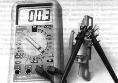
Pic. 2.9. After setting up the multimeter to measure resistance (Ohm) you can measure the resistance between two terminals. When checking for continuity, a low reading indicates continuity, a high reading or shown corresponding to infinity indicates an open
Search for an open in the electrical circuit
10. When diagnosing an electrical circuit suspected of an open circuit, it is quite difficult to visually detect the cause of the malfunction, since it is difficult to inspect the terminals for corrosion or a violation of the quality of their contacts due to limited access to them. A sharp twitch of the connector housing on the sensor or its wiring harness in many cases leads to the restoration of conductivity. Keep this in mind when trying to identify the cause of a failure in an electrical circuit that is suspected to be open. Malfunctions that occur only occasionally can be caused by oxidized terminals or loose contacts.
11. Diagnosing faults in electrical circuits is quite simple, provided it is clear that current is flowing to all electrical loads (lamp, electric motor, etc.) from the battery through wires through switches, relays, fuses, fuses, then returns to the battery through «mass» car. Any problems associated with the failure of electrical equipment can only be caused by the interruption of the supply of electric current to them from the battery or return to it.
Electrical connectors
12. Most of the electrical connectors on the vehicles in question are multi-pin and have a plastic housing. Reliability of joining sections of such connectors is ensured by snapping of the locking tabs mounted in the plastic housing of the connectors. The mating sections of large connectors, some of which are used under the dash, are most often bolted together with a bolt through the center of the connector.
13. To disconnect connectors equipped with plastic latches, a small screwdriver is usually used, with which the locking tabs should be carefully pressed out. Then disconnect the connector. To avoid accidental damage to individual wires and pins in connectors, pull only on the plug, never on the wiring harness. Before disconnecting the connectors, examine it carefully. Often blocking elements are not visible at first glance. In addition, many connectors have more than one pair of latches.
14. Connectors always consist of two halves, the pins of one of which go inside the sockets of the other. When studying the schematic representations of the connectors, first of all, try to determine which of its halves is shown in the figure: from the side of the wiring harness or from the side of the element. Remember that the pins of one half of the connector are always placed mirrored with respect to the pins of the other, i.e. the pin shown on the right side of the connector will have the mating pin located on the left side.