
Precautionary measures
1. Before performing work on electrical equipment, disconnect the wire from the negative terminal of the battery.
2. If the battery needs to be disconnected for a check or repair, be sure to disconnect the negative cable first (-) terminal that is connected to the body (weight) car.
3. When carrying out welding work, disconnect the battery and connectors of the electronic control unit.
4. Do not open the ECU cover unless absolutely necessary, as the ECU's integrated circuit may be damaged by static electricity.
Switching on thermal fuses
1. Remove the thermal fuse.
2. To turn on the fuse, insert the needle into the hole and press it.
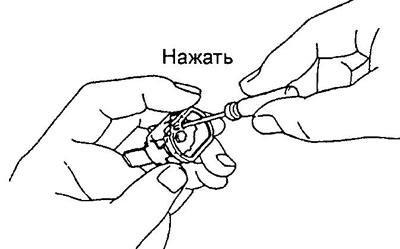
3. Check up an ohmmeter conductivity between conclusions.
If there is no continuity after switching on the fuse, install a new one with the same characteristics.
Note: If the fuse continues to open after replacement, check the circuit it protects for a short circuit.
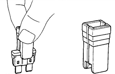
Replacing fuses
1. Before servicing, turn off the ignition and all electrical appliances.
2. Install fuses only of the regulated current rating.
Note: Do not use a higher rated fuse or any other items ("bugs") instead of a blown fuse. This may cause more serious damage or fire.
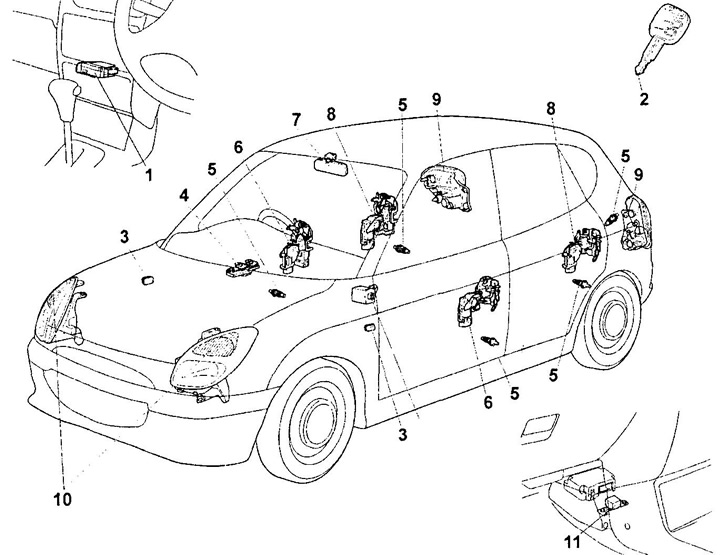
Location of components (door locks, lights and lighting).
1 - Multiplex control unit,
2 - main ignition key,
3 - turn signal repeater,
4 - main power window control switch,
5 - door limit switch,
6 - electric drive of the front door lock,
7 - interior lighting lamp,
8 - electric lock of the rear side door,
9 - rear combination lamp,
10 - headlights,
11 - collision sensor.
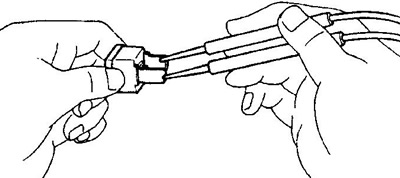
3. Remove and install the fuse only in a straight line, without unscrewing or swinging. Otherwise, the contacts may move apart too wide and the fuse will not hold in them.
Note: Use the fuse tool to remove and install the fuse (see picture).
4. If the fuse blows again after replacing the fuse, check the circuits for an open or short circuit.
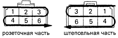
Connector identification
1. The pins in the female connector are numbered from top left to bottom right.
2. The pins of the plug connector are numbered from top right to bottom left.
Note: when multiple connectors are used in one node, the names of each connector are indicated (letter of the alphabet) and contact number.
3. Unless otherwise noted, all connectors are shown on the open side with the lock up.
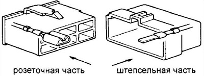
4. When disconnecting the connectors, do not pull on the wires and be careful when disconnecting the retainer clips.
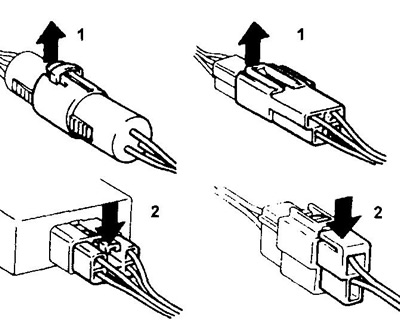
1 - press,
2 - click.