
Attention! Models covered in this manual are equipped with an assisted restraint system (SRS), better known as «airbag system». To prevent accidental deployment of airbags, which could result in injury, be sure to deactivate the airbag system before working near components of the airbag system (see paragraph 25).
1. Disconnect the wire «masses» from battery (see paragraph 1 of chapter 5).
2. Remove the upper and lower casings of the steering column.
Ignition switch
3. Disconnect the ignition switch electrical connector (pic. 7.3).
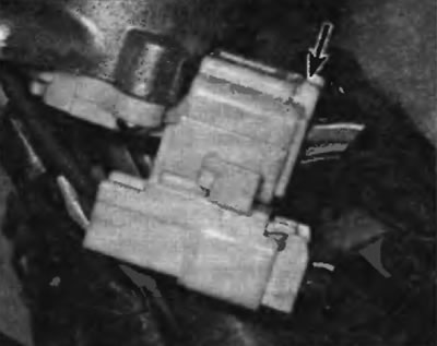
Pic. 7.3. To disconnect the electrical connector of the ignition switch, press the locking element
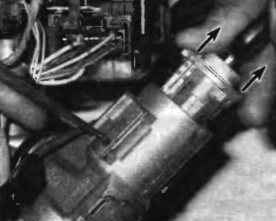
4. Turn out screws of fastening of the switch of ignition (pic. 7.4) and remove the switch from the lock cylinder housing.
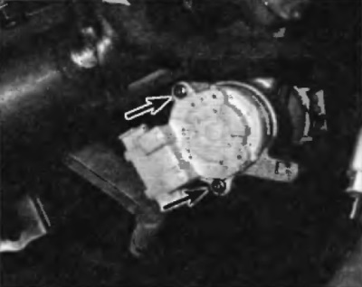
Pic. 7.4. To disconnect the ignition switch from the lock cylinder housing, unscrew the two screws
5. Installation is carried out in the reverse order of removal.
Lock cylinder
6. Turn the ignition key to the ACC position (accessories).
7. If the car is equipped with an immobilizer, disconnect the electrical connector of the immobilizer module, then pull out the module and the lock cylinder illumination ring as a unit (pic. 7.7).
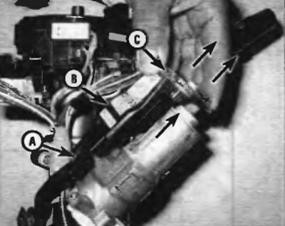
Pic. 7.7. To remove the immobilizer module and lock cylinder illumination ring, disconnect the electrical connector (A), then pull out the immobilizer (IN) and light ring (WITH) from the lock cylinder
8. Using an awl or punch, press the lock pin of the lock cylinder and remove the lock cylinder from the body (pic. 7.8, a, b)
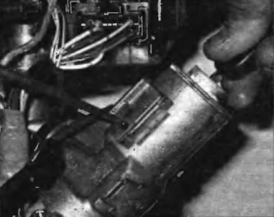
Pic. 7.8, a. To remove the lock cylinder from the housing, turn the ignition switch to the ACC position, press the pin in the small hole in the lock cylinder housing with an awl...
Pic. 7.8b....and remove the lock cylinder
9. To install the lock cylinder, press down on the lock pin and slide the lock cylinder into the housing until the pin fits back into the mounting hole in the housing.
10. Further installation is performed in the reverse order of removal.