
Removing
Note. Axial backlash of camshafts check up before their removal.
Removal in the following order:
- turn off the ignition and disconnect the wire «masses» from the storage battery;
- remove the cylinder head cover;
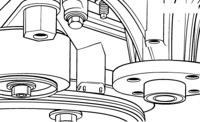
Pic. 3.52. Alignment of the mark on the vibration damper with the TDC or 0 sign on the front cover of the chain
Pic. 3.55. Alignment of the marks on the camshaft sprockets with the marks on the camshaft bearing caps (VVT pulley/actuator assembly visible on intake camshaft)
- set the piston of the first cylinder to TDC on the compression stroke, while the mark on the vibration damper must be aligned with the TDC or 0 sign on the chain front cover (smris. 3.52), and the marks on the camshaft sprockets must be aligned with the marks on the camshaft bearing caps (see fig. 3.55);

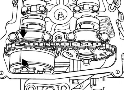
Pic. 3.70. Places for applying alignment marks on the chain, opposite the marks on the camshaft sprockets
- apply paint to the chain with alignment marks located opposite the marks on the camshaft sprockets (pic. 3.70);
Note. There are two marks on the camshaft sprockets. Some marks are designed to set the camshafts at the TDC of the piston of the first cylinder, and others to align with the colored marks of the chain.
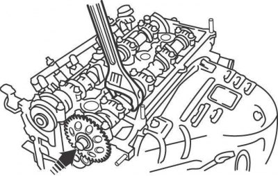
Pic. 3.61. Using wrenches to keep the camshaft from turning and loosening the sprocket mounting bolt
- holding the camshaft from turning by the hexagon with a wrench, unscrew the bolt securing the sprocket to the camshaft by a few turns (see fig. 3.61);
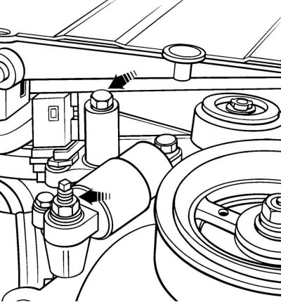
Pic. 3.56. Arrangement of bolts of fastening of the mechanism of a tension of a chain
- remove the chain tensioner and crank angle sensor from the front chain cover (see fig. 3.56);
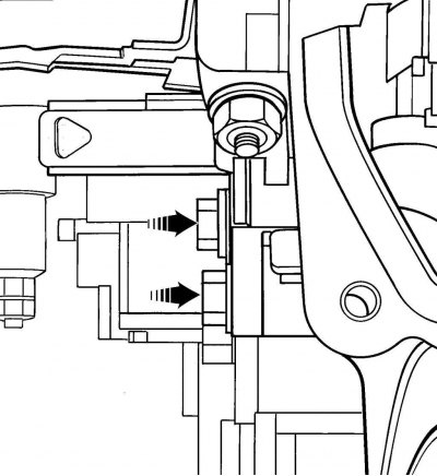
Pic. 3.57. Arrangement of nuts of fastening of a tensioner of a chain
- unscrew the nuts and remove the chain tensioner from the back of the cover (see fig. 3.57);
- Remove bolts securing sprockets to camshafts. Remove the chain from the camshaft sprockets and remove the sprockets;
- check the axial clearance of the camshafts. Install a bracket with a dial indicator on the engine block so that the measuring tip of the indicator rests against the end of the camshaft;
- move the camshaft along the axis to one side until it stops and set the indicator to 0. Move the camshaft along the axis to the other side until it stops and fix the value on the indicator. If the clearance of the intake camshaft exceeds the allowable value, check the condition of bearing No. 1 of the camshaft. If the bearing surface is worn, replace the bearing. If the clearance of the exhaust camshaft exceeds the allowable value, it is necessary to replace the camshaft and / or the cylinder head;
- check if the variable valve timing system valve is located (VVT) on the back of the intake camshaft;
- after removing the sprockets, extend the chain as far as possible, and secure it to the bulkhead of the engine compartment with soft wire. This will prevent the chain from falling into the motor when performing the following operations. Also put a clean rag on top of the chain cover;
- check for marks on the camshaft bearing caps. The lids are numbered from 1 to 5 and the letters I and E. The letter I (Intake) indicates that the cover is installed on the intake camshaft, and E (Exhaust) - exhaust valves. There are also arrows on the covers, which, when installing the covers, should be directed towards the chain;
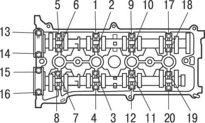
Pic. 3.75. The sequence of tightening the bolts of the camshaft bearing caps
- in the reverse order to tightening, gradually loosen, and then completely unscrew the bolts securing the camshaft bearing caps in several passes (see fig. 3.75);
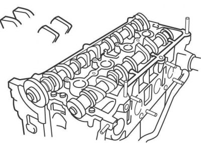
- remove the bearing caps and camshafts from the cylinder head. Note the position of the camshafts, as they must be in the same positions during installation;
- wipe off oil and mark the pushers, remove them from the cylinder head with a magnetized tool and position them so that they are in place during installation.
Examination
Visually inspect the cams and camshaft bearing journals for wear, corrosion, metal enveloping, and discoloration indicating local overheating.
Check the condition of the teeth on the sprockets. The teeth on the sprocket are symmetrical and if one side of the teeth is worn out, the sprocket must be replaced along with the chain.
Check the condition of the camshaft bearings in the cylinder head for signs of corrosion, scratches and wear.
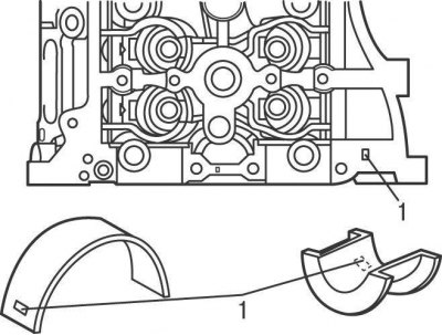
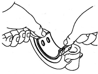
Pic. 3.71. The location of the bearing No. 1 of the intake camshaft and the place (1) which are marked
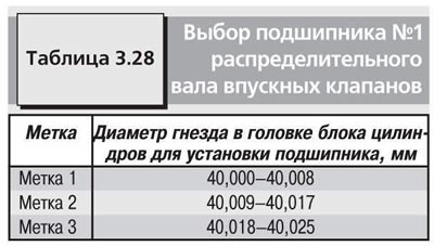
If the working surfaces of bearing No. 1 of the intake camshaft are damaged, replace it in accordance with the data given in table 3.28 (pic. 3.71).
Measure the diameter of each camshaft bearing journal with a micrometer and record the values. Necks are measured at several points, both in diameter and in length, this will reveal ovality and taper, if any. The nominal value of the diameter of the necks of the camshaft bearings: bearing No. 1–35.971–35.985; the rest - 22.959–22.975 mm. If the diameter of any neck is less than the nominal value, replace the camshaft.
Install the camshaft bearing caps to the cylinder head and secure with bolts. Measure the inside diameter of each respective camshaft bearing and record the values. To determine the radial clearance, subtract the diameter of the corresponding camshaft journal from the bearing diameter. Compare the clearance value with the technical data. If the clearance exceeds the limit, replace the camshaft and/or cylinder head.
Measure the height of the camshaft cams with a micrometer. Compare the cam height with the technical data. If the cam height is less than the limit, replace the camshaft.
Measure the radial runout of the camshaft. Install the camshaft to the cylinder head. Install the bracket with the dial indicator on the cylinder head so that the measuring tip of the indicator rests on the middle journal of the camshaft, and set the indicator to 0. Slowly turn the camshaft and note the change in the indicator readings.
Move the camshaft along the axis to the other side until it stops and fix the value on the indicator. The maximum permissible value of the radial runout is 0.03 mm. If the radial runout is greater than the limit, replace the camshaft.
Check each pushrod for wear and tear.
Measure the outer diameter of each pusher, and the corresponding pushrod sockets. To determine the clearance, subtract the tappet diameter from the socket diameter. The nominal value of the gap is 0.033–0.059 mm, the maximum allowable value is 0.079 mm. If the gap exceeds the maximum allowable value, replace the pushers.
Installation
Install in the following order:
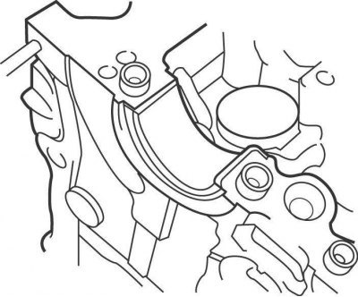
Pic. 3.72. Installing bearing No. 1 of the intake camshaft in the cylinder head
Pic. 3.73. Installing bearing No. 1 of the intake camshaft in the bearing cap
- if bearing No. 1 of the intake camshaft was removed, install it in the cylinder head (pic. 3.72) and bearing cover (pic. 3.73);
- lubricate the pushers with engine oil and install them in the places in which they were before removal;
- lubricate the necks and camshaft cams with engine oil;
Pic. 3.74. Setting the cams of the first cylinder
- install the camshafts so that the cams of the shafts of the first cylinder are directed in different directions from each other, at an angle of 30°upwards from the horizontal plane (pic. 3.74), and the dowel pins were pointing up;
- install the camshaft bearing caps and secure them with bolts, finger-tight at this stage;
- in the sequence shown in Figure 3.75, turning 1/4 turn in one pass, screw in the cover fastening bolts and tighten them to the torques given in the technical data;
- align the teeth of the camshaft sprocket with the chain links, matching the marks made before removal, and install the sprockets on the camshafts so that the shaft pins fit into the holes on the back of the sprockets;
- check that the piston of the first cylinder is set to TDC on the compression stroke, while the mark on the vibration damper must be aligned with the TDC or 0 sign on the chain front cover (see fig. 3.52), and the marks on the camshaft sprockets must be aligned with the marks on the bearing caps (see fig. 3.55). Make sure that the alignment marks on the chain before removal are located opposite the marks on the camshaft sprockets (see fig. 3.70);
- in turn, holding the camshaft with a wrench from turning by the hexagon, screw the bolts securing the sprockets to the camshafts (see fig. 3.61);
- install the chain tensioner.
Further installation is carried out in the reverse order of removal.