
Removing
Remove the chain on a cold engine in the following order:
- turn off the ignition and disconnect the wire «masses» from the storage battery;
- remove the accessory drive belt;
- remove the generator;
- remove the cylinder head cover;
- if present, remove the ABS unit;
- tighten the parking brake and block the rear wheels with stops;
- Loosen the right front wheel nuts. Raise the front of the car and place it on stands. Remove the right front wheel and the right front wheel arch mudguard;
- drain the coolant;
- remove the bolts, remove and set aside the power steering pump with hoses connected to it. Fasten the pump to the body with a soft wire;
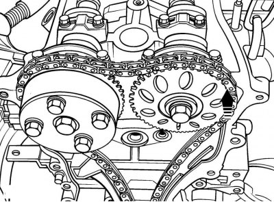
Pic. 3.52. Alignment of the mark on the vibration damper with the TDC or 0 sign on the front cover of the chain
- set the piston of the first cylinder to TDC on the compression stroke, while the mark on the vibration damper must be aligned with the TDC or 0 sign on the chain front cover (see fig. 3.52), and the marks on the camshaft sprockets must be aligned with the marks on the camshaft bearing caps (pic. 3.55);
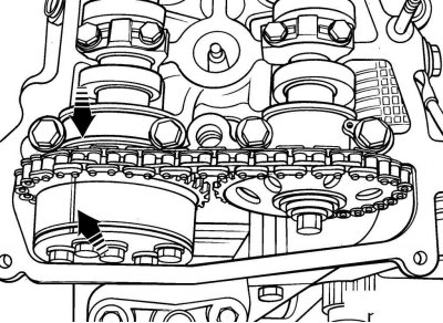
Pic. 3.55. Alignment of the marks on the camshaft sprockets with the marks on the camshaft bearing caps (VVT pulley/actuator assembly visible on intake camshaft)
- remove the pulley/vibration damper from the crankshaft, but do not rotate the crankshaft. If the crankshaft has rotated, return it to the position corresponding to the installation of the piston of the first cylinder at TDC on the compression stroke;
- jack, through a wooden block installed under the oil pan, raise the engine so that its weight is taken up by the jack.
- remove the left engine mount;
Pic. 3.56. Arrangement of bolts of fastening of the mechanism of a tension of a chain
- remove the chain tensioner (pic. 3.56) and the crank angle sensor from the front chain cover. Turn out a bolt of fastening of a plait of wires of the gauge of an angle of rotation of a cranked shaft to a cover of a chain;
- remove the oil pan;
- unscrew the bolts and remove the wire harness holder from the chain cover;
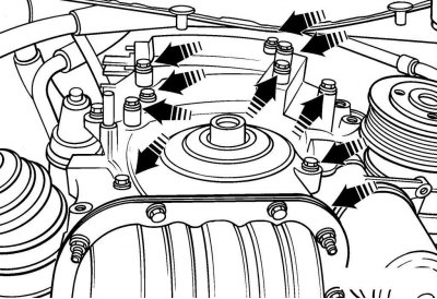
Pic. 3.57. Arrangement of nuts of fastening of a tensioner of a chain
- remove the nuts (pic. 3.57) and remove the chain tensioner from the back of the cover;
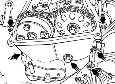
Pic. 3.58. The location of the upper bolts of the chain cover
Pic. 3.59. The location of the lower bolts of the chain cover
- remove the bolts (pic. 3.58, 3.59) and pry bar separate, and remove the chain cover from the cylinder block. Note the location of the bolts as they are of different lengths;
- remove the crankshaft angle sensor;
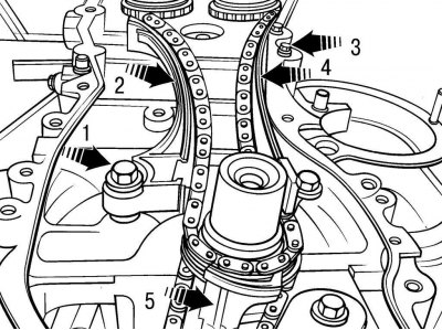
Pic. 3.60. Chain guides and tensioner: 1 - hinge bolt; 2 - chain tensioner; 3 - bolts for fastening the guide chain; 4 - fixed chain guide; 5 - lower chain guide
- remove bolts 1.3 (pic. 3.60) and remove tensioner 2 and lower chain guide 5;
- remove the chain from the camshaft sprockets and the sprocket together with the chain from the crankshaft. If the chain is to be reinstalled, mark the front of the chain with chalk, marker or paint. If, during installation, the chain rotates in the opposite direction, due to the existing development of the chain, the wear of the elements of the gas distribution mechanism will increase and the noise generated by the chain will increase;
- remove the fixed chain guide 4;
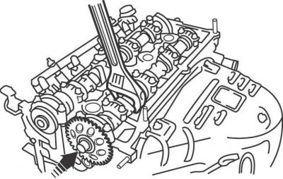
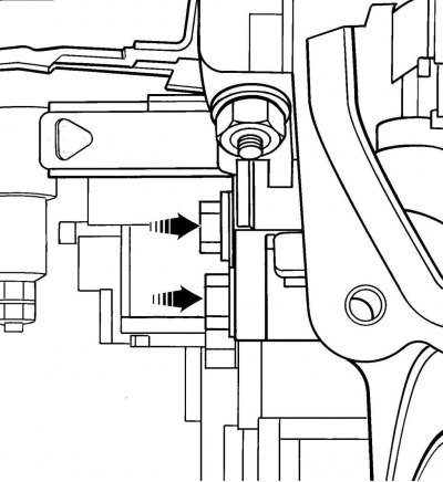
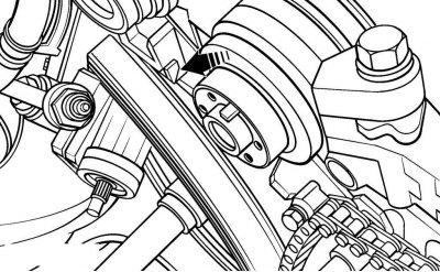
Pic. 3.61. Using wrenches to keep the camshaft from turning and loosening the sprocket mounting bolt
- holding the camshaft with a wrench from turning by the hexagon, unscrew the mounting bolt and remove the sprocket from the camshaft (pic. 3.61).
Attention! On the intake camshaft, in addition to the sprocket, a pulley / drive assembly for the variable valve timing system is installed (VVT). When removing the intake camshaft sprocket, unscrew only the central bolt of the pulley / actuator of the variable valve timing system. Do not remove the 4 bolts securing the variable valve timing pulley/actuator to the sprocket.
Examination
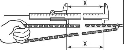
Pic. 3.62. Measuring the distance between chain links: X = 122.6 mm for the timing chain between 16 rollers or 8 chain links; X = 52.4 mm for oil pump drive chain between 8 rollers or 4 chain links
Visually check the condition of the parts for wear and damage. Check chain links for cracks, worn rollers and side plates. Check the condition of the sprocket teeth, which should be symmetrical. Tension the chain and measure the distance between the 8 links of the chain, which should be equal to 122.6 mm (pic. 3.62). Carry out this check on several sections of the chain. If the chain lengthens, replace the chain and sprockets as a set.
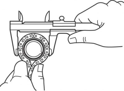
Pic. 3.63. Measuring the sprocket diameter using the chain rollers
Wrap a chain around each sprocket and measure the diameter of the sprocket against the chain rollers (pic. 3.63). If the resulting size exceeds the minimum chain diameter, replace the chain and sprockets as a set.
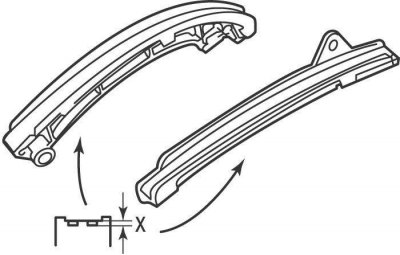
Pic. 3.64. Places for measuring the depth of the grooves on the chain guides: X = no more than 1.0 mm
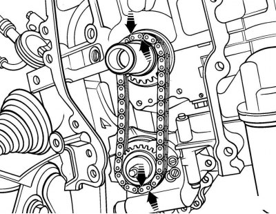
Pic. 3.95. Matching the colored marks on the chain with the marks on the sprockets
Check chain guides for excessive wear. Keep in mind that slight wear on the guides is normal. The depth of the grooves on the chain guides should be no more than 1.0 mm (pic. 3.64). If there is excessive wear, check the chain guide lube hole on the front of the cylinder block for dirt or blockage (see fig. 3.95).
Installation
Install in the following order:
1) use a scraper to remove the remnants of the old sealant from the mating surfaces of the chain cover and the cylinder head and block;
2) make sure the camshafts are turned with the dowel pins up to the position «12 h», then install both sprockets, aligning the pin hole on the back of the sprocket with the camshaft pin. Coat the threads of the sprocket mounting bolts with a locking compound to prevent their self-unscrewing, and screw the bolts by hand. Holding the camshaft from turning by the hexagon with a wrench, tighten the sprocket mounting bolt to a torque of 54 Nm (see fig. 3.61);
3) if necessary, tighten the camshafts to a position in which the marks on the camshaft sprockets are aligned with the marks on the camshaft bearing caps (see fig. 3.55);
4) if the crankshaft was rotated from TDC, rotate it to a position where the keyway is not pointing up, to the position «12 h»;
5) install fixed chain guide 4 (see fig. 3.60);
6) Slide the chain onto the crankshaft sprocket, aligning the #1 colored mark on the chain with the mark on the sprocket. Install the sprocket with the chain installed on it on the crankshaft, then install the lower chain guide;
Attention! There are three colored marks on the chain. Mark #1 is located at a greater distance from the other two marks, which are located close to each other.
Pic. 3.65. Matching the colored marks on the chain with the marks on the camshaft sprockets when installing the chain
7) install the chain on the fixed chain guide shoe, then on the exhaust camshaft sprocket, and finally on the intake camshaft sprocket. Check that the colored marks on the chain line up with the marks on the sprockets (pic. 3.65). When installing the chain, eliminate the sagging of the right branch of the chain;
Pic. 3.66. The location of the protrusion on the tension mechanism
8) remove the slack on the left side of the chain, install the chain tensioner, screw in the hinge bolt and tighten it to 19 Nm. After installation, make sure that the tab on the tensioner (pic. 3.66) does not pass the stop to the cylinder head;
9) recheck that the piston of the first cylinder is at TDC on the compression stroke, while the mark on the vibration damper must be aligned with the TDC or 0 mark on the front cover of the chain (see fig. 3.52), and the marks on the camshaft sprockets must be aligned with the marks on the camshaft bearing caps (see fig. 3.55);
10) install the crankshaft angle sensor and the ring, the F mark on which should be directed outward;
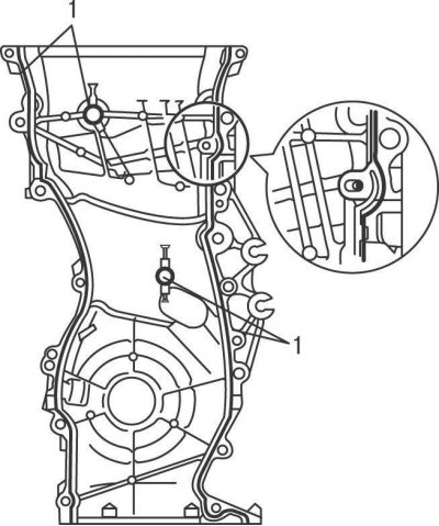
Pic. 3.67. Places (1) applying a layer of sealant to the mating surfaces of the chain cover
11) Apply a coat of 3-4 mm RTV Sealant to the mating surfaces of the chain cover 1 (pic. 3.67). Also apply a small amount of sealant to the junction of the head and cylinder block. Install the engine cover and secure with the bolts in their original positions. Gradually, over several passes, tighten the bolts to the required torque;
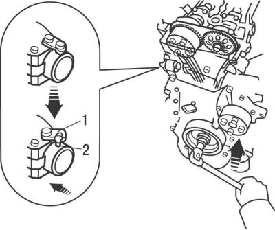
Pic. 3.68. Raising the ratchet pawl and sliding the plunger of the chain tensioner to its original position (inside)
12) Set the chain tension plunger to its original position as follows:
- raise the ratchet pawl and push the plunger inward until it reaches the bottom limit (pic. 3.68);
- hook the hook on the body of the tension mechanism to the pin on the plunger, as a result of which the plunger will be fixed in its original position;
13) lubricate the O-rings of the tensioner plunger with engine oil and install it in the chain cover;
14) install the pulley / vibration damper on the crankshaft;
Pic. 3.69. To release the hook on the mechanism housing from the pin on the plunger, it is necessary to slightly turn the engine crankshaft counterclockwise: 1 - hook; 2 - pin
15) slightly turn the engine crankshaft counterclockwise to set the chain tension. In this case, hook 1 (pic. 3.69) on the body of the tension mechanism must be released from pin 2 on the plunger, as a result of which the plunger will tension the chain. If the plunger does not release on its own, depress the chain tensioner and release the pin on the plunger with a screwdriver blade;
16) turn the engine crankshaft clockwise a few revolutions and set the piston of the first cylinder to TDC on the compression stroke. Check that the mark on the vibration damper is aligned with the TDC or 0 mark on the chain front cover (see fig. 3.52), and the marks on the camshaft sprockets are aligned with the marks on the camshaft bearing caps (see fig. 3.55).
Further installation is carried out in the reverse order of removal.