
Attention: do not open the cover of the control unit unnecessarily, (if you touch the terminal of the integrated circuit, it can be damaged by static electricity).
Fault #1: No switching
1. Warm up the engine to a temperature of 80°C and the gearbox to 50-80°C.
2. Connect a voltmeter to the terminals "TT" and *E1" diagnostic socket.
3. If the voltage at the output "TT" does not change in proportion to the degree of opening of the throttle valve, then check the voltage between the terminals "STP" ("VC") And "E1" connector of the automatic transmission control unit at different positions of the brake pedal.
Normal Voltage:
- models up to 1996:
- brake pedal pressed: 10-14 V
- brake pedal released: 0 V
- models since 1996:
- brake pedal pressed: 7.5-14 V
- brake pedal released: 0-1.5 V
- A) If the voltage is normal, then:
- break in the power cable of the automatic transmission control unit.
- malfunction in the throttle position sensor circuit;
- breakage or short circuit in the wire "TT".
- b) If the voltage is different from the specified - a malfunction in the brake light switch circuit.
4. Disconnect the solenoid connector and road test. The gearbox must operate in the following gears:
- Range "D": 4 gear
- Range "2": 3 (А540Н-4) broadcast
- Range "L": 1 gear
If the gearbox does not work as indicated, the gearbox is faulty.
5. Connect the connector of the solenoid valves and measure the voltage at the terminals "TT" And "E1" diagnostic socket.
- A) If the voltage changes smoothly from 0 V to 7 V, then:
- faulty gearbox;
- Solenoid valves are defective.
- b) If the voltage changes from 0V to 5V, see fault #3. '
- V) If the voltage changes from 0 to 2 V, then on the range "D" check the voltage between the terminals "2" And "E1" automatic transmission control unit connector.
Rated voltage:
- pre-1996 models: 10-14V
- models since 1996: 7.5-14 V
If the voltage is not correct, replace the automatic transmission control unit. If the voltage is normal, there is a malfunction in the start inhibit switch circuit.
- G) If the voltage does not change (0 V), then on the range "D" check the voltage between the terminals "L" And "E1" control unit connector.
Rated voltage:
- pre-1996 models: 10-14V
- models since 1996: 7.5-14 V
If the voltage is not normal, replace the automatic transmission control unit.
If the voltage is normal, there is a malfunction in the start inhibit switch circuit.
Fault #2: Shifting Is Either Too Late or Too Early
1. Warm up the engine to a temperature of BO'C and the gearbox to 50-80°C.
2. Connect a voltmeter to the terminals "TT" And "E1" diagnostic socket.
3. If the voltage at the output "TT" does not change in proportion to the degree of opening of the throttle valve, then check the voltage between the terminals "STP" GW/K") And "E1" connector of the automatic transmission control unit at various positions of the brake pedal: Normal voltage:
- models before 1996
- brake pedal released 0 V
- brake pedal pressed: 10-14V
- models since 1996
- brake pedal released: 0-1.5 V
- brake pedal pressed: 7.5-14 V
- A) If the voltage is normal then:
- a break in the power cable of the automatic transmission control unit and the engine.
- malfunction in the throttle position sensor circuit.
- breakage or short circuit in the wire "TT".
- b) If the voltage is different, the problem is with the brake light switch.
4 Models prior to 1996 If the output voltage "TT" changes in proportion to the degree of opening of the throttle valve, then the control unit or automatic transmission is faulty.
5 Models since 1996 If the output voltage "TT" changes in proportion to the degree of throttle opening, then check the voltage between the terminals "PWR" And "E1" (since 1996 - also "MANU" And "E1") connector of the automatic transmission and engine control unit.
Voltage at the position of the automatic transmission mode selection switch
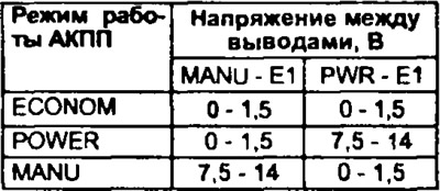
If the voltage is not normal, then the automatic transmission mode selection switch is faulty.
If the voltage is normal, then the automatic transmission and engine control unit is faulty or the automatic transmission is faulty.
Fault #3: No upshifts (after warming up)
1. Road test with the solenoid valve block connector disconnected by moving the selector sequentially from position "L" in position "2" And "D". Upshifts must occur in the gearbox. If upshifts do not occur, then the gearbox is faulty.
2. Connect the connector of the solenoid valves and check how the voltage changes at the output "TT" diagnostic connector (normally from 0 to 4 V).
- A) If the voltage smoothly changes from 0 V to 7 V then:
- faulty gearbox;
- Solenoid valves are defective.
- b) If the voltage changes smoothly from 0 V to 2 V, then on the range "D" check the voltage between the terminals "2" And "E1" connector of the automatic transmission and engine control unit. Voltage:
- pre-1996 models: 10-14V
- models since 1996: 7.5-14 V
If the voltage is not normal, then replace the automatic transmission and engine control unit.
If the voltage is normal, there is a malfunction in the start inhibit switch circuit.
- V) If the voltage does not change (0 V), then on the range "D" check the voltage between the terminals "L" And "E1" automatic transmission control unit connector. Voltage:
- pre-1996 models: 10-14V
- models since 1996: 7.5-14 V
If the voltage is not correct, replace the automatic transmission and engine control unit.
If the voltage is correct:
- a malfunction in the start inhibit switch circuit;
- malfunction of the start inhibit switch.
3. Check the voltage between the terminals "OD2" And "EG connector of the automatic transmission and engine control unit at different positions of the overdrive switch.
Voltage at switch position:
- "ON"
- pre-1996 models: 10-14 V
- models since 1996: 9-14 V
- "OFF"
- pre-1996 models: 0 V
- models since 1996: 3 V or less
If the voltage differs from the rated voltage, then there is a malfunction in the overdrive switch circuit.
Models since 1996 If the voltage is normal, then the automatic transmission control unit is faulty.
4. Models up to 1996 Check voltage between terminals "ODi" (models before 1996) And "E1" automatic transmission and engine control unit connector If the voltage differs from the nominal, replace the automatic transmission and engine control unit. The voltage is about 5 V.
5. Models up to 1996 If the voltage between the terminals "OD," And "E, "connector of the automatic transmission control unit and the engine with the connector of the electronic control unit of speed maintenance disconnected (Cruise control) is different from the nominal value, replace the cruise control electronics (Cruise control). Otherwise, replace the electronic automatic transmission and engine control unit or the wiring harness of the electronic speed control unit (Cruise control).
Fault number 4: there is no torque converter lock (after warming up)
1. Warm up the engine to a temperature of 80°0 and the gearbox to 50-80°C.
2. Carry out a road test. Connect a voltmeter to the leads "TT" And "E1" diagnostic socket. Measure the lock-up voltage of the torque converter. If it is 7 V, then:
- flooded the solenoid valve for controlling the torque converter lock-up clutch,
- faulty gearbox;
- Faulty torque converter lockup clutch.
3. Check the voltage between the terminals "STP" ("VC") And "EG connector of the automatic transmission and engine control unit at different positions of the brake pedal; Normal Voltage:
- Models before 1996:
- brake pedal released 0 V
- brake pedal pressed 10-14 8
- Models since 1996:
- brake pedal released no more than 1.5 V
- brake pedal pressed 7.5-14 V
- A) If the voltage is normal, there is a malfunction in the throttle position sensor circuit or in the power circuit of the automatic transmission and engine electronic control unit.
- b) If the voltage is different from the specified - a malfunction in the brake light switch circuit.
Fault number 5 (A245E): no torque converter lock-up with controlled clutch slip (after warming up)
1. Warm up the engine to a temperature of 80°C and the gearbox to 50-80°C.
2. Measure the voltage between the terminals "THW" And "E1" connector of the electronic control unit. Normal voltage 0.7-1.0V
If the voltage is abnormal, then an open or short circuit in the engine coolant temperature sensor circuit or a malfunction of the engine coolant temperature sensor.
3. Check the voltage between the terminals "TNO" ("OIL") And "E1" connector of the electronic control unit. Normal voltage is 2 V.
If the voltage is not correct, then an open or short circuit in the automatic transmission fluid temperature sensor circuit.
4. Check the voltage between the terminals "OD2" And "E1" control unit connector at different overdrive switch positions: Voltage at switch position:
- "ON": 9-14V
- "OFF": no more than 3 V
If the voltage differs from the rated voltage, then the engine start inhibit switch is faulty.
5. Check the voltage between the terminals "PWR" And "E1" (since 1996 - also "MANU" And "E1") connector of the automatic transmission and engine control unit.
Voltage at the position of the automatic transmission mode selection switch
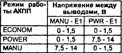
If the voltage differs from the nominal, then the switch for selecting the automatic transmission operating mode is faulty.
6. Check the voltage between the terminals "TT" And-"E1" diagnostic socket.
Normal Voltage:
- throttle closed no more than 0.6 V
- throttle open 7.6-8.7 V
If the voltage is not normal, then check the voltage between the terminals "STP" And "E1" connector of the automatic transmission and engine control unit.
Normal Voltage:
- brake pedal released no more than 1.5 V
- brake pedal pressed 7.5-14 V
- A) If the voltage is not correct, then the brake light switch is faulty.
- b) If the voltage is normal, then an open or short circuit in the throttle position sensor wiring or a faulty throttle position sensor.
7. Disconnect the connector of the automatic transmission and engine electronic control unit. Check resistance between terminals "NC2+" And "NC2-" connector of the automatic transmission and engine control unit. Resistance 560-680 Ohm.
If the resistance differs from the nominal, then an open or short circuit in the circuit of the speed sensor No. 2 or the speed sensor No. 2 is faulty.
8. Check the resistance between the terminals "SL" And "E1" connector of the electronic control unit. Resistance 11-15 Ohm.
If the resistance differs from the nominal, then an open or short circuit in the torque converter clutch control solenoid valve circuit or a malfunction of the valve itself.
9. Check the resistance between the terminals "SLU+" And "SLU-" connector for the automatic transmission and engine control unit. Resistance - 5.1-5.5 ohms.
If the resistance differs from the nominal, then an open or short circuit in the circuit of the solenoid valve for controlling the quality of blocking or a malfunction of the valve itself.
10. Check the voltage between the terminals "TT" And "E1" diagnostic socket.
The voltage with the brake pedal depressed is not more than 2.7 V.
If the voltage does not correspond to the nominal, then replace the automatic transmission fluid.
11. Move the overdrive switch to the "OFF", the automatic transmission mode selection switch to position "OFF" (NORM mode), the air conditioner switch to position "OFF".
12 Accelerate the vehicle to a speed of 60 km/h and release the accelerator pedal. If the voltage between the terminals "TT" And "E1" of the diagnostic connector corresponds to the specified one until the vehicle speed drops to 30 km / h, then:
- faulty automatic transmission.
- the solenoid valve for controlling the torque converter lock-up clutch is sticking.
- the torque converter lock-up quality control solenoid valve sticks. Voltage 2.7-3.4 V.
If the voltage does not match the specified, then the automatic transmission and engine control unit is faulty.