
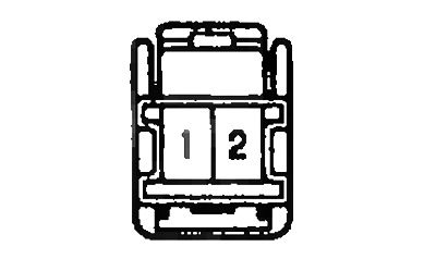
Headlight relay test
1. Check for continuity between terminals "1" And "2".
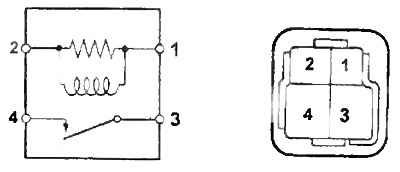
2. Check for continuity between terminals "3" And "4" when battery voltage is applied between terminals and "2".
Checking the taillight relay, fog lamp relay, cornering light relay
1. Check for continuity between terminals "1" And "2".
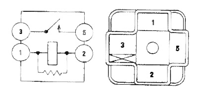
2. Check for continuity between terminals "3" And "5" when battery voltage is applied to the terminals "1" And "2".
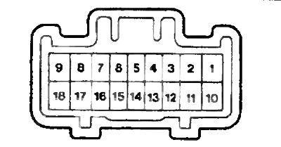
Combination Switch Test
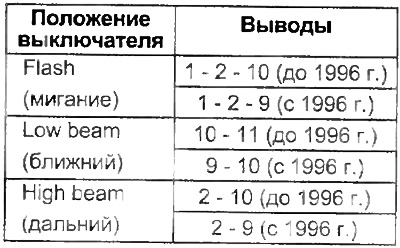
Light switch test
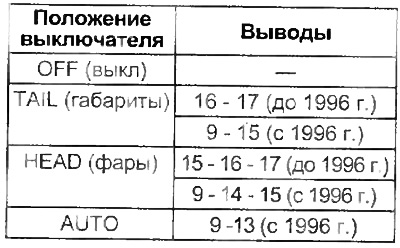
Models up to 1996.
Models since 1996
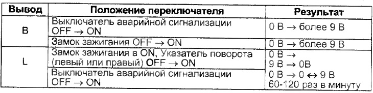
Checking the turn signal breaker relay
Checking the headlight switch
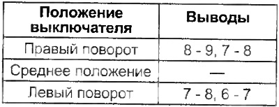
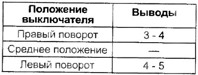
Checking the turn signal switch
Checking the light switch when turning
Checking the fog light switch
Check for continuity between pins "12" And "13" if the switch is in position "ON". As well as the lack of conductivity between the terminals "12" And "13" if the switch is in position "OFF".
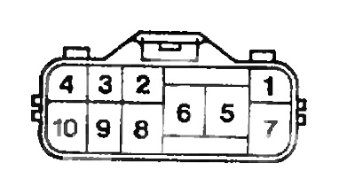
Hazard switch test
Check for continuity between pins "2" And "3" in any position of the switch.
Check for continuity between pins "7" And "10" if the switch is in position "OFF".
Check for continuity between pins "7" And "8", and "4", "5", "6" And "9" if the switch is in position "ON".
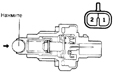
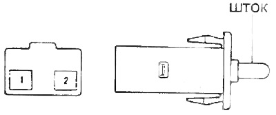
Check of the switch of lanterns of a backing
Check for continuity between terminals "1" And "2" by pressing the switch ball.
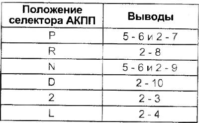
Checking the start inhibit switch and the automatic transmission selector position sensor
Check up conductivity between conclusions of a socket at various positions of the selector.
 |  |
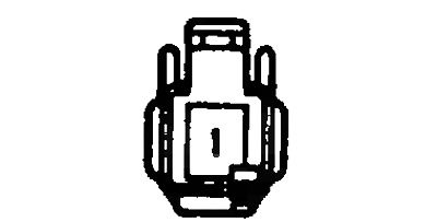
Checking limit switches
Check that there is no continuity between the connector pin and the bracket when the switch stem is pressed.
Checking the glove box lighting limit switch (ZX, AX, VX)
Check that there is no continuity between the terminals when the switch stem is pressed "1" And "2" connector.
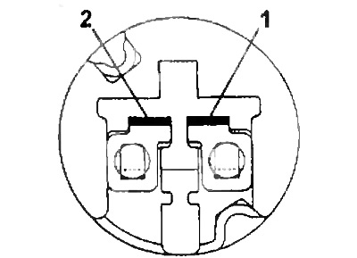
Checking the brake light switch
Conductivity between terminals "1" And "2" when pressing the brake pedal.
Checking the upper brake light (on the spoiler)
let me down "+" battery to the output "1", and to the conclusion "2" and make sure the brake light comes on.
Note: Observe the correct polarity of the battery connection.
Checking the integrated relay (release models before 1996)
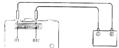
1. Checking the key left in the ignition warning system.
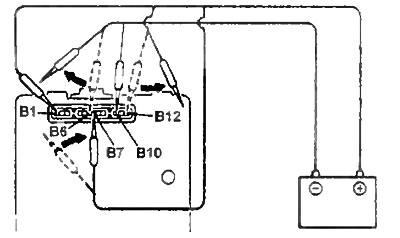
A) Connect battery terminal "IN 1", and to the conclusion "AT 10", "B5" And "AT 6" and make sure the buzzer sounds.
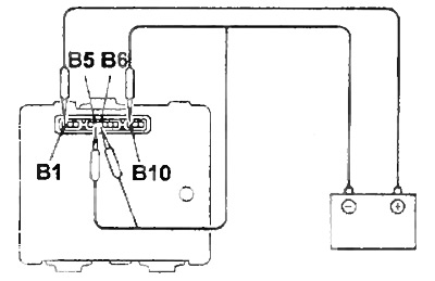
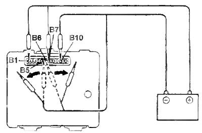
b) Make sure that when disconnecting (connection) battery wires from (To) conclusions (am), specified in paragraph (A):
- detachment from "AT 5" battery.
- detachment from "AT 6" battery.
- connection to "AT 7" battery.
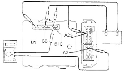
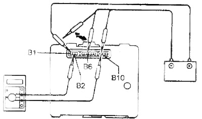
2. Checking the operation of the warning system about not switched off dimensions (except ZX, VX).
A) Connect "+" battery to the output "IN 1", and to the conclusion "AT 10" and check that the buzzer sounds when the battery is connected to the terminal "AT 12" and to "AT 6".
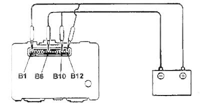
b) Make sure that when disconnecting (connection) battery wires from (To) conclusions (am), specified in paragraph (A):
- detachment from "AT 12" "+" battery.
- detachment from "AT 6" "-" battery.
- connection to "AT 7" "+" battery.
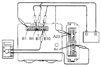
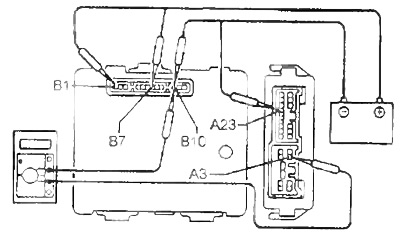
3. Checking the operation of the automatic lighting shutdown system (ZX, VX).
Rear dimensions
A) Connect "+" battery to the output "IN 1", and to the conclusion "AT 10". Check for continuity between leads "A4" And "AT 10" when connecting "+" battery to the output "AT 7" And "-" To "A23".
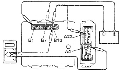
b) Make sure there is no change in conductance between the leads "A4" And "AT 10" when disconnected "+" battery off output "AT 7".
V) Make sure there is no continuity between the terminals "A4" And "AT 10" when connecting the battery to "AT 6".
G) Check for continuity between leads "A4" And "AT 10" when connected "+" battery to the output "AT 7".
Headlights
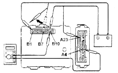
A) Connect "+" battery to the output "IN 1", A "-" to the conclusion "AT 10". Check for continuity between leads "AZ" And "AT 10" when connecting "+" battery to the output "AT 7" and to "A22".
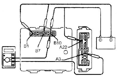
b) Make sure there is no change in conductance between the leads "AZ" And "AT 10" when disconnected "+" battery off output "AT 7".
V) Make sure there is no continuity between the terminals "AZ" And "AT 10" when connecting the battery to "AT 6".
G) Check for continuity between leads "AZ" And "AT 10" when connected "+" battery to the output "AT 7".
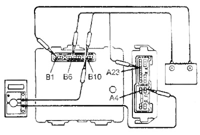
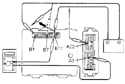
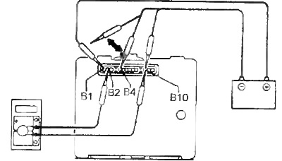
4. Checking the operation of the ignition lock illumination system.
A) Connect battery terminal "IN 1", A "-" to the conclusion "AT 10".
b) Check for continuity between leads "AT 2" And "AT 10" when connected "-" battery to the output "AT 6".
V) Make sure there is no continuity between the terminals "AT 2" And "AT 10" when the battery is disconnected from the output "AT 6".
G) Check for continuity between leads "AT 2" And "AT 10" when connecting the battery to the terminal "AT 4".
d) Make sure there is no continuity between the terminals "AT 2" And "AT 10" when the battery is disconnected from the output "AT 4".
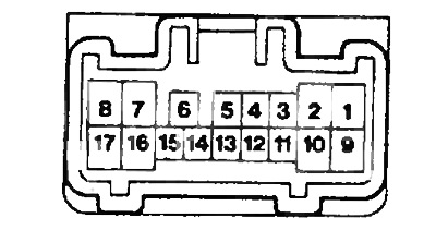
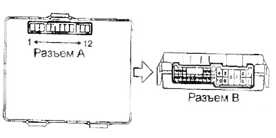
Checking the integrated relay (release models since 1996)
1. Checking the key left in the ignition warning system.
A) Connect battery terminal "At 16", and to the conclusion "A10", check that the buzzer sounds when the battery is connected to the terminals "A5" And "A6".
b) Make sure that when disconnecting the battery wires from the terminals indicated in paragraph (A):
- detachment from "A5" "-" battery.
- detachment from "A6" "-" battery.
- connection to "A7" "+" battery.
2. Checking the operation of the warning system about not switched off dimensions.
A) Connect battery terminal "At 16", and to the conclusion "A10" and make sure you hear a buzzer sound when connecting "+" battery to the output "A12" and to "A6".
b) Make sure that when disconnecting the battery wires from the terminals indicated in paragraph (A) sound stopped:
- detachment from "A12" "+" battery.
- detachment from "A6" "-" battery.
- connection to "A7""+" battery.
3. Checking the operation of the ignition lock illumination system.
A) Connect "+" battery to the output "B16", and to the conclusion "A10".
b) Check for continuity between leads "A2" And "A10" when connected "-" battery to the output "A6".
V) Make sure there is no continuity between the terminals "A2" And "A10" when disconnected "-" battery off output "A6".
G) Check for continuity between leads "A2" And "A10" when connected "-" battery to the output "A4".
d) Make sure there is no continuity between the terminals "A2" And "A10" 5 seconds after shutdown "-" battery off output "A4".