



Contents: Checking the operation of the heater…↓ Checking and repairing rear window…↓ Checking the mirror heater ↓
Checking the operation of the heater switch
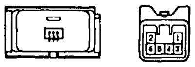
Models before 1996
1. Check the conductivity between the terminals of the switch connector.
- a) Check for absence of conductivity between terminals "2" and "3" in the "OFF" position and presence of conductivity in the "ON" position.
- b) Check for conductivity between terminals "1" and "4" (backlight) in all switch positions.
2. Check the operation of the timer.
- a) Connect the "+" of the battery to terminal "2", "-" to terminal "3".
- b) Connect a 3.4 W test lamp between terminals "1" and "4".
- c) Set the switch to the "ON" position, check that the indicator lamp and backlight lamp light for 12-18 minutes, then go out.
3. Check the backlight lamp. Connect the battery to terminals "1" and "4", check that the lamp lights up.
Models after 1996
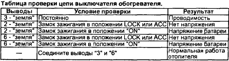
1. Check for conductivity between terminals "1" and "4" in all switch positions.
2. Check the operation of the timer.
- a) Connect the "+" of the battery to terminal "2", "-" to terminal "3".
- b) Connect the "+" of the battery through a 3.4 W test lamp to terminal "6".
- c) Set the switch to the "ON" position, check that the indicator lamp and backlight lamp light for 12-18 minutes, then go out.
3. Disconnect the connector from the switch and check the circuit from the wire side according to the table.

If the switch operates differently than described, replace it.
Checking and repairing rear window defroster wires
Note:
- When cleaning the glass, use a soft, dry cloth, wipe the glass parallel to the heater wires. Try not to damage the wires.
- It is prohibited to use detergents and compounds containing abrasive particles.
- When measuring voltage, wrap the end of the negative terminal of the tester with tin foil and press the edge of the foil to the wire with your finger.
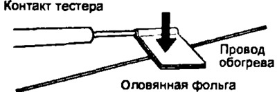
1. Checking for broken wires
- a) Turn on the ignition and the rear window heater.
- b) Measure the voltage at the center of each thermocouple wire as shown in the figure.

- c) If the voltage is about 5V, then the wire is normal.
- d) If the voltage is about 10 V, then there is a break in the wire between the middle and the side bus of the thermoelement.
- d) If the voltage is about 0 V, then there is a break in the wire between the middle and the "ground"
2. Finding the location of the break in the wire.
- a) Connect the "plus" of the voltmeter to the "+" side bus of the thermocouple.
- b) Wrap the "minus" of the voltmeter with foil. Connect the foil to the thermocouple wire at the side bus and slowly move it to the opposite end (to "ground").
- c) The point at which the voltmeter needle deviates from zero by several volts is the break point.
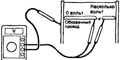
Note: If there is no wire break, the voltmeter will show 0 V at the side bus of the thermocouple and, when the voltmeter contact is moved to the opposite end of the wire, the voltage will gradually increase to approximately 12 V.
3. Repair of wires.
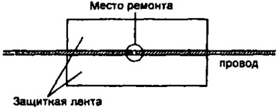
- a) Clean the ends of the wire at the break point with a solvent and stick on protective tape (see fig.).
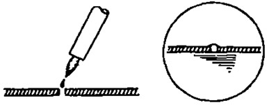
- b) Mix the repair compound thoroughly and apply a drop of the substance to the wire using a brush. Repair compound: DUPONT PASTE No.4817 or similar.
- c) After a few minutes, remove the protective film and leave to harden for 24 hours.
Checking the mirror heater
1. Connect the "+" of the battery to terminal "4", "-" to terminal "5" of the connector.
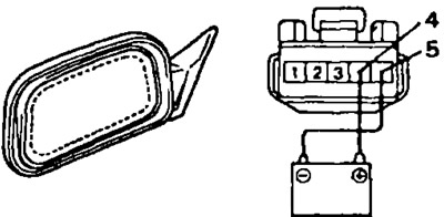
2. Check that the mirror is heating up. If the mirror is not heating up, replace it.