
Coolant temperature switch (3S-FE, 4S-FE)
1. Drain the coolant and remove the coolant temperature switch.
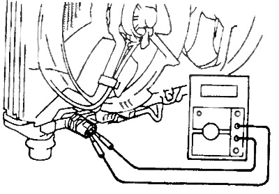
2. Check up the gauge switch on temperature of a cooling liquid.
A) Using an ohmmeter, check that there is no continuity between the sensor-switch leads at temperature. coolant above 93°C.
b) Using an ohmmeter, check the presence of conductivity between the outputs of the sensor-switch at a coolant temperature of not more than 83°C.
3. Install the coolant temperature switch.
4. Fill in coolant.
Main relay of the fuel injection system
1. Remove the main relay of the injection system.
2. Check the resistance of the relay winding.
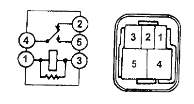
A) Use an ohmmeter to check for continuity between the terminals "1" And "3" (resistance - 60-90 Ohm). Resistance between terminals "2 and "4" - 0 ohm
b) Then use an ohmmeter to verify that there is no continuity between the terminals "4" And "5" (resistance - infinity).
3. Check relay operation.
A) Apply battery voltage to terminals "1" And "3" relay connector.
b) Use an ohmmeter to check for continuity between the terminals "2" And "4".
b) Use an ohmmeter to check for continuity between the terminals "4" And "5".
If the conditions in points 1 and 2 are not met, replace the relay.
4. If necessary, the relay housing can be removed and, before throwing it away, try to eliminate the cause of the failure. To do this, clean all contacts, and check the resistance of the windings in two directions, since there may be diodes that shunt the windings.
If the winding resistances are the same in both directions, then there are no diodes, and you can connect the battery in any order. If not, then connect the battery with the correct polarity.
5. Reinstall the relay.
Electric fan relay
1. Disconnect the negative plug from the storage battery.
2. Remove the electric fan relay.
3. Check the fan relay (3S-FE, 4S-FE).
Check for continuity between terminals "1" And "2" (50 -80 ohm) u3" And "4" (0 ohm).
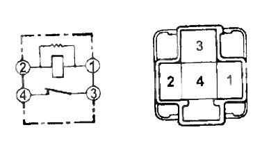
If these conditions are not met, replace the relay.
(3C-T)
A) Check continuity between leads with an ohmmeter "86" And "85", And "30" And "87a".
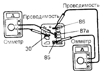
b) Apply battery voltage to the relay outputs "86" And "85".
V) Check with an ohmmeter that there is no continuity between the relay terminals "30" And "87a".
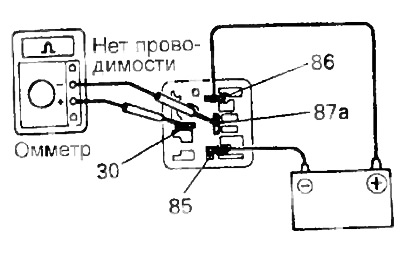
If these conditions are not met, replace the relay.
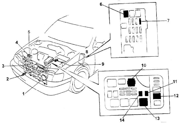
The layout of the elements of the electric fan control system on the car (3S-FE, 4S-FE).
1 - electric fan No. 1,
2 - sensor switch for coolant temperature,
3 - electric fan No. 1,
4 - relay No. 2 electric fan (models with air conditioning),
5 - relay No. 3 electric fan (models with air conditioning),
6 - fuse "AM" 40A,
7 - fuse "GAUSE" 10A,
8 - fuse block,
9 - main fuse "MAIN" 10A,
10 - relay No. 1 electric fan,
11 - fuse "RDI" 30A,
12 - fuse "ALT 100A",
13 - the main relay of the engine.
Checking the fan motor
1. Disconnect the fan electrical connector.
2. Connect the ammeter and battery to the fan connector as shown in the figure.
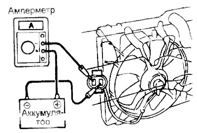
After making sure that the fan rotates freely, read the ammeter
Rated current:
ZS-T:
- electric fan No. 1 - 13.2 A
- electric fan No. 2 - 9 - 11 A
3S-FE, 4S-FE:
- electric fan No. 1 - 3.2-4.4 A
- electric fan №2 (models with air conditioning) - 5.8- 7.4 A
If the ammeter reading is out of range, replace the fan motor.
3. Connect the electrical connectors of the fans.