
Fuel temperature sensor
Note: On some early models, the sensor is missing, a plug is installed in its place.
1. Verification
A) Turn off "ignition".
b) Disconnect the fuel temperature sensor connector.
V) Place a container under the injection pump to collect fuel.
G) Remove the fuel temperature sensor.
d) Immerse the sensor element of the fuel temperature sensor in water of a known temperature.
e) Measure the resistance between the fuel temperature sensor terminals at the test points.
Connector Color - Dark Gray
Temperature - Resistance
20°C - ~2500 Ohm
40°C - ~1100 Ohm
60°C - ~600 Ohm
80°C - ~300 Ohm
Pic. 16 Checking the fuel temperature sensor
Boost pressure sensor
It is connected by a rubber tube to the intake manifold. The pressure in the intake manifold of a turbocharged engine varies from a vacuum of the order of 100 mm Hg. Art. at idle to an overpressure of 0.98 bar at full load and the turbine turned on.
Marking:
- SENSOR ASS/
- TURBO PRESSURE
- Manufacturer: TOYOTA
- Connector Color - Black
Checking the supply voltage
1. Turn off "ignition".
2. Disconnect the boost pressure sensor connector.
3. Turn on "ignition".
4. Measure the voltage between the connector terminals.
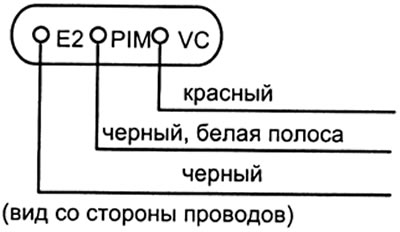
Terminal - purpose
1. E2 - "Earth"
2. R/M - sensor signal
3. VC - power supply +5 V
Terminals - Voltage
VC and E2 - 4.5-5.5 V
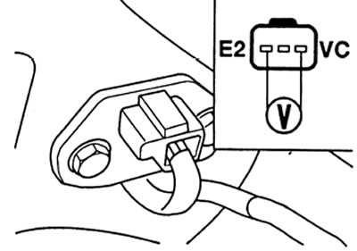
Pic. 17 Checking the boost pressure sensor
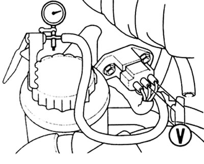
Checking the boost pressure sensor
1. Turn off "ignition".
2. Remove the vacuum tube from the boost pressure sensor.
3. Provide access to the sensor connector terminals without disconnecting the connector.
4 Turn on "ignition".
5 Measure the voltage between the terminals "PIM" And "E2" connector.
6 Compare with specification voltage.
7. Use a vacuum pump to create a vacuum on the sensor.
8 Measure the voltage between the connector terminals.
Vacuum - Voltage drop
100 mmHg st - 0.3 - 0.5 V
200 mmHg st - 0.6 - 0.8 V
300 mmHg st - 0.95 - 1.15 V
9. Compare voltage drop with specification data.
10. Pressurize the transmitter.
11. Measure the voltage between the connector terminals.
Pressure - voltage increase
0.19 bar - 0.4-0.7 V
0.39 bar - 0.9- 1.2 V
0.59 bar - 1.4-1.7 V
0.79 bar - 2.0-2.3 V
0.98 bar - 2.5-2.8 V
12. Compare voltage rise with specification data.
Voltage between terminals "PIM" And "E2" plug on running engine
Terminals PIM and E2
Operating mode - Voltage
Warm-up - 1.4 V
Idling - 0.8 V
at 3000 rpm - 1.5 V
Pic. 18 Checking the boost pressure sensor
Intake air temperature sensor
The air temperature sensor measures the temperature of the air after the air cleaner in order to subsequently calculate the volume of air entering the engine cylinders and issue a command to inject the appropriate amount of fuel. Always works in tandem with an absolute air pressure sensor in the intake manifold Installed in the intake duct on the rear side of the air cleaner
Two-pin connector without marking. black color
Purpose - Wire color
brown - "Earth"
yellow - signal
Resistance test
1. Turn off "ignition".
2. Disconnect the sensor connector.
3. Measure the ambient air temperature.
4. Measure the resistance and between the sensor terminals.
Temperature - Resistance
20°C - ~2500 Ohm
40°C - ~1100 Ohm
60°C - ~600 Ohm
80°C - ~300 Ohm
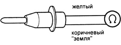
Pic. 19 Checking the resistance of the intake air temperature sensor.
Engine coolant temperature sensor
The sensor is located on the thermostat.
Examination
1. Turn off "ignition".
2. Disconnect the sensor connector.
3. Relieve any residual pressure in the cooling system.
4. Remove the sensor from the engine.
5. Immerse the sensor element in water of known temperature.
6. Measure the resistance between the sensor terminals at the test points.
Connector Color - Gray
Temperature - Resistance
20°C - ~2500 Ohm
40°C - ~ 1000 Ohm
60°C - ~ 600 Ohm
80°C - ~300 Ohm
On a warm diesel engine, the voltage on the sensor is ~ 7 V
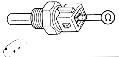
Fig. 20 Checking the coolant temperature sensor.
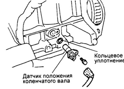
Crankshaft position sensor
It also serves as a crankshaft speed sensor. Located on the block next to the flywheel at the bottom of the crankcase.
Connector Color - Black
Resistance (cold engine) — 19 - 32 Ohm
(warm engine) — 24 - 37 Ohm
Resistance test
1. Turn off "ignition".
2. Disconnect the sensor connector.
3. Measure the resistance between the sensor terminals
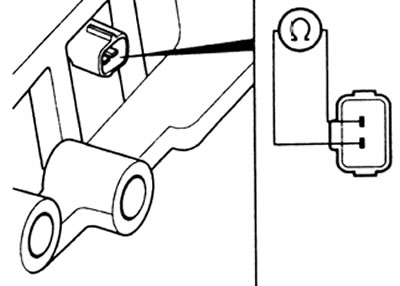
Pic. 21 Checking the resistance of the crankshaft position sensor
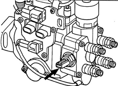
Speed sensor (position of the injection pump shaft)
It is installed in the injection pump. On the part of the circuits, it is also designated as an engine speed sensor. This is possible because, in essence, it is also a speed sensor for the injection pump, which is unambiguous with the engine speed.
The sensor is installed in the front of the injection pump from above vertically
Connector - white
Temperature - Resistance
20°C - 205-255 ohm
Resistance test
1. Turn off "ignition".
2. Disconnect the sensor connector.
3. Measure the resistance between the sensor terminals.
Pic. 22 Speed sensor (fuel pump shaft position sensor)
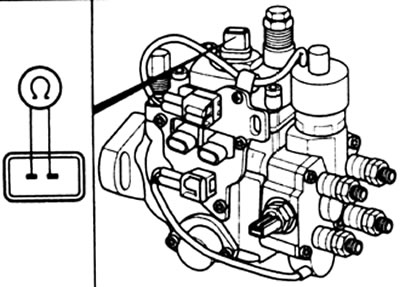
Correction resistors for injection pump
Resistance test
1. Turn off "ignition".
2. Disconnect each resistor connector in turn.
3. Measure the resistance between the resistor terminals.
Temperature - Resistance
20°C - 100 - 2500 Ohm
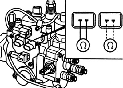
Pic. 23 Checking the injection pump resistors
Relay control system
Checking work
Note: observe the polarity of the power connection, otherwise the relay may be damaged.
1. Turn off "ignition".
2. Remove the relay.
3. Measure the resistance between terminals 3 and 4 of the relay.
4. Connect battery power to the indicated terminals (1 and 2) relay.
5. Measure the resistance between terminals 3 and 4 of the relay.
Changeover contact terminals
3 and 4
Power - Resistance
no - infinity
yes - nil
("Plus" battery to terminal 1)
("Minus" battery to terminal 2)
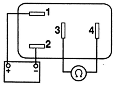
Pic. 24 Checking the control relay