
Note: checking and adjusting the thermal clearances in the valves is carried out on a cold engine.
1. Disconnect the negative plug from the storage battery.
2. Disconnect the wiring harness.
3. Disconnect the crankcase ventilation hoses.
4. Disconnect high voltage wires.
5. Remove the cylinder head cover.
6. Set the piston of the 1st cylinder to the TDC position on the compression stroke.
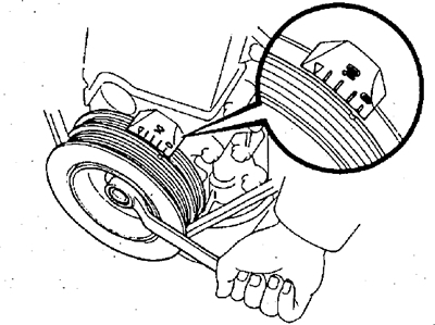
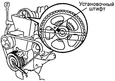
A) Turn the crankshaft pulley clockwise and align the groove on the pulley with the mark "ABOUT" on cover No. 1 of the camshaft drive belt.
b) Make sure the hole on the camshaft drive pulley aligns with the mark on the bearing cap.
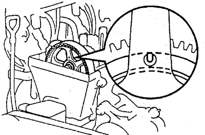
If this condition is not met, then turn the crankshaft clockwise 1 turn (360°) and again align the groove on the pulley with the corresponding mark.
7. Check the thermal gap in the valves marked in the figure:
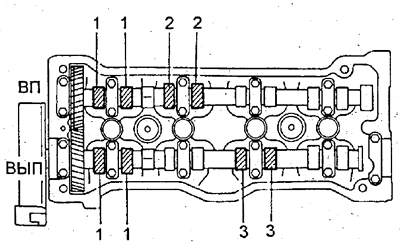
A) Using a feeler gauge, measure the clearance between the valve lifter and the camshaft lobe.
b) Make a note of any clearance that is outside the specified limits. These values will be used to select the required shim size.
Nominal thermal clearance in valves (on a cold engine):
- inlet - 0.15-0.25 mm
- graduation - 0.25-0.35 mm
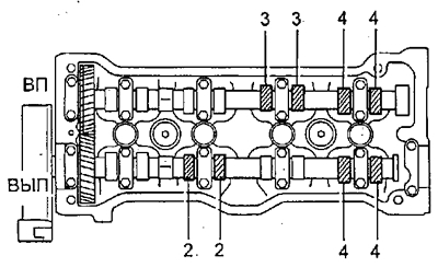
8. Rotate the crankshaft 1 turn (360°) and again align the groove on the pulley with the corresponding mark, as indicated in paragraph 6, and check the clearances in the valves marked in the figure by repeating the procedure in paragraph 7.
9. Adjust the thermal clearance in the valves:
Notes:
- - In these engines, to adjust the thermal clearance in the valves, the dismantling of the camshafts is required.
- - Since the camshaft end play is very small, it must be kept in a horizontal position when the camshaft is removed. otherwise, the camshaft thrust washer seat in the cylinder head may be damaged, which may cause the camshaft to seize or break. Similar requirements must be observed when installing camshafts.
- - The methods for adjusting the clearance of the intake and exhaust valves are slightly different from each other.
9.1. Adjust the thermal gaps in the intake valves.
9.1.1. Remove the intake camshaft.
A) Rotate the crankshaft pulley so that the hole in the auxiliary gear (on which the auxiliary gear is installed on the camshaft drive gear) turned out to be at the top, this allows the cams of the 1st and 3rd cylinders to equally press on the pushers of the corresponding valves.
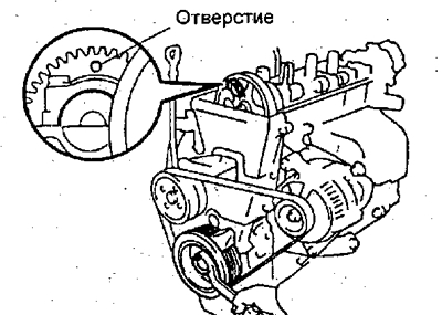
b) Turn away 2 bolts and remove a cover of the 1st bearing of a camshaft.
V) Attach the camshaft sub gear to the drive gear with a set bolt.
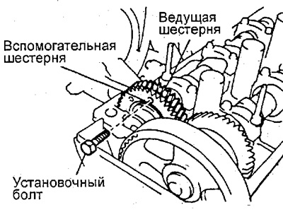
Recommended dimensions of the set bolt: diameter - 6 mm, thread pitch - 1.0 mm, length - 16-20 mm.
Note: When removing the camshaft, make sure that the twisting force transmitted to the auxiliary gear from the spring is removed by the above operation.
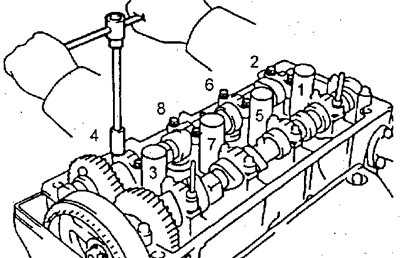
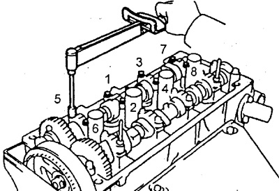
G) Evenly loosen and remove the 8 camshaft bearing cap bolts in several passes in the sequence shown in the figure. Then remove the bearing caps and camshaft.
Note:
- - If the camshaft cannot be removed when performing the above steps, reinstall bearing cap No. 3 and tighten it with two bolts.
- - Then sequentially release and unscrew the bolts, at the same time trying to pull the camshaft by the gear.
- Do not try to remove the camshaft with great effort or with the help of additional levers and fixtures.
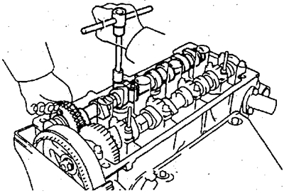
9.1.2. Remove the adjusting washer with a small screwdriver.
9.1.3. Determine the size (thickness) adjusting washer, providing clearance in accordance with the specifications.
A) Measure the thickness of the removed shim with a micrometer.
b) Using the formula, determine the thickness of the new shim, which will provide the required thermal clearance in the valves:
For intake valves - N=T+ (A-0.20) mm
- N - new washer thickness
- T - thickness removed (spent) washers
- A - measured clearance in the valve
V) Select a shim that comes closest to the calculated thickness.
Note: shims have 16 sizes (thickness values) from 2.55 mm to 3.30 mm through 0.05 mm.
9.1.4. Install a new shim on the valve lifter.
9.1.5. Install the intake camshaft.
A) Rotate the crankshaft pulley and position the exhaust camshaft so that its locating pin is higher than the edge of the cylinder head.
b) Apply grease to the thrust surfaces of the camshaft.
V) Connect the intake camshaft gear to the exhaust camshaft gear, matching the timing marks of both gears.
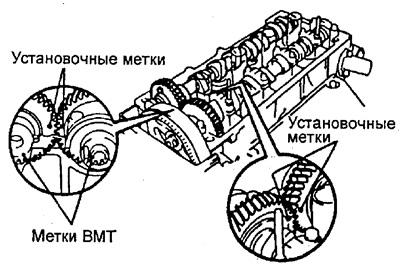
Note: it is necessary to distinguish alignment marks from TDC marks and do not use the latter in this case.
G) After that, start the camshaft in the bearing bed, keeping the gears engaged.
Note: this position of the camshaft allows the cams of the first and third cylinders to evenly press the pushers of the respective valves.
d) Reinstall the four camshaft bearing caps.
e) Apply a light coat of engine oil to the threads and under the heads of the camshaft bearing cap bolts.
and) Install and evenly tighten the 8 bearing cap bolts in several passes in the sequence shown.
- Tightening torque - 13 Nm
h) Remove the set bolt.
And) Install the cover of the 1st bearing with the mark ("arrow") forward.
Note: If the 1st bearing cap does not fit, use a screwdriver to move the camshaft back.
To) Apply a light coat of engine oil to the threads and under the camshaft bearing cap bolt heads.
l) Install and evenly tighten the 2 front bearing cap bolts in several passes;
- Tightening torque - 13 Nm
9.1.6. Check valve clearances.
9.2. Adjust the thermal gaps in the exhaust valves.
9.2.1. Remove adjusting washers.
A) Rotate the crankshaft so that the lobe of the variable valve cam is oriented upwards.
b) Position the valve lifter notch towards the front of the vehicle.
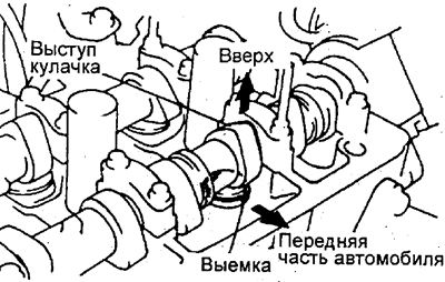
V) Using fixture (A), press the pusher and install the fixture (IN) between the camshaft and pushrod. Then remove the tool (A).

Note:
- - Type fixture (IN) at a slight angle from the side indicated by the number "9", as it shown on the picture. In this case, the notch should be in the position shown in the figure.
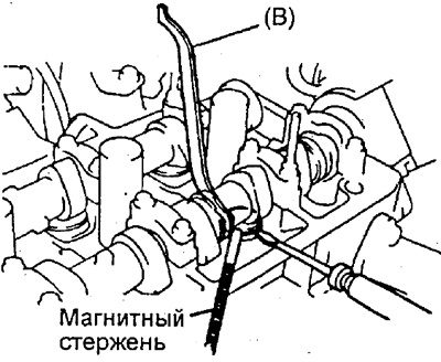
- - Fixture (IN) should not be inserted too deep, so as not to pinch the adjusting washer. To prevent jamming, insert the tool smoothly from the side of the intake camshaft, as shown in the figure.
- - Cam profile makes fixture installation difficult (IN) under the 3rd cam on the intake camshaft side. To replace this shim, tool (IN) should be installed on the side of the exhaust valves.
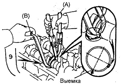
G) Remove the adjusting washer with a small screwdriver and a magnetic bar.
9.2.2. Determine the size (thickness) adjusting washer, providing clearance in accordance with the specifications.
A) Measure the thickness of the removed shim with a micrometer.
b) Using the formula, determine the thickness of the new shim, which will provide the required thermal clearance in the valves:
For exhaust valves - N=T + (A-0.30) mm.
- N is the thickness of the new washer.
- T - thickness removed (spent) washers.
- A is the measured clearance in this valve.
V) Select a shim that comes closest to the calculated thickness.
Note: shims have 16 sizes (thickness values) from 2.55 mm to 3.30 mm through 0.05 mm.
9.2.3. Install a new shim.
A) Install the washer on the valve lifter.
b) fixture (A) press the pusher and remove the fixture (IN).
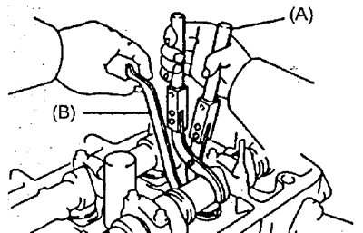
9.2.4. Check the valve clearance.
10. Establish a cover of a head of the block of cylinders.
A) Remove old sealant.
b) Apply a layer of fresh sealant in the areas shown in the illustration.
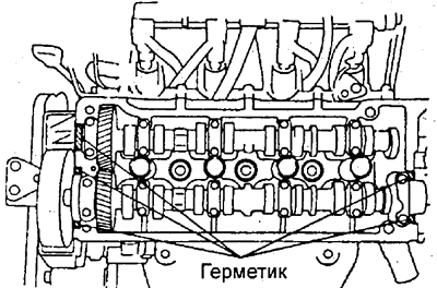
V) Install the gasket under the cylinder head cover.
G) Install the block head cover, securing it with 4 nuts installed on the sealing washers.
- Tightening torque of nuts - 6 Nm
11. Connect high voltage wires.
12. Connect the hoses of the crankcase ventilation system.
13. Connect the wiring harness.
14. Connect the negative plug to the storage battery.