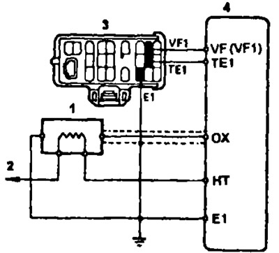
Scheme of switching on the oxygen sensor (3S-FE, 4A-FE, 4S-FE, 7A-FE): 1 - oxygen sensor, 2 - to the main relay of the fuel injection system, 3 - diagnostic connector, 4 - electronic control unit
1. Warm up the engine to normal operating temperature.
2. Measure the oxygen sensor feedback voltage.
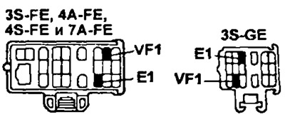
3S-FE, 3S-GE. 4A-FE, 4S-FE, 5E-FE
- A) Connect the positive lead of the voltmeter to the "VF1" diagnostic connector, and the negative terminal - to the terminal "E1" and check according to the given algorithm.
7A-FE
- A) Start the engine.
- b) Warm up the engine to normal operating temperature.
- V) Connect the positive lead of the voltmeter to the "VF1" diagnostic connector, and the negative terminal - to the contact "E1".
- G) Let the engine run at 2500 rpm for 2 minutes.
- d) Let the engine run at idle speed for 10 minutes.
- e) Increase engine speed rapidly (2-3 times).
- and) Set the speed to 1500 rpm.
- h) Measure voltage between terminals "VF1" And "E1".
Rated value: no more than 1 V.
- And) Set to idle.
- To) Measure voltage between terminals "VF1" And "E1".
Rated value: (at 700±50 rpm) not less than 4.3 V.
3. (3S-FE, 3S-GE, 4A-FE, 4S-FE. 7A-FE) Measure the resistance of the oxygen sensor heater by connecting an ohmmeter to the terminals "+V" And "NT".
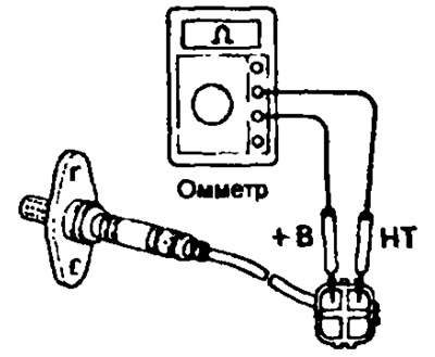
Rated resistance (at t = 20°C):
- 3S-FE, 3S-GE, 4A-FE and 4S-FE: 5.1-6.3 ohms
- 7A-FE: 1.5-2.10 ohm
If the resistance value is out of range, replace the oxygen sensor.
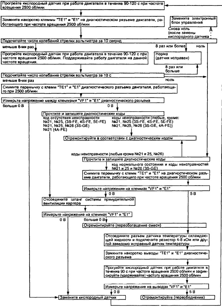
Algorithm for troubleshooting the oxygen sensor