
Attention! If the vehicle is equipped with electronically controlled air suspension, turn off the suspension height control switch before raising the vehicle.
Attention! Do not turn the steering shaft when the steering gear is removed from the vehicle. Otherwise, you may damage the airbag coil spring. To prevent the shaft from rotating, turn the ignition key to the lock position or pass the seat belt over the steering wheel and fasten it.
Removing
1. Put the car on the platform and point the front wheels straight ahead. Loosen the front wheel nuts. Raise the front of the car and place secure supports under it. Apply the parking brake and remove the wheels. Remove the lower engine cover (in the presence of).
2. Place a drain pan under the steering gear. Disconnect the pressure and return pipes of the power steering (pic. 20.2, a) and plug the ends to prevent large amounts of fluid from escaping and dirt from entering the system. Disconnect the pipeline support bracket at the top of the steering gear.
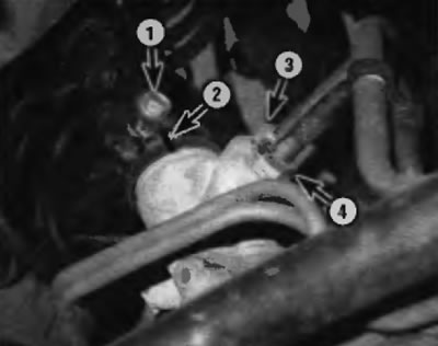
Pic. 20.2, a. Elements of fastening and connection on the steering mechanism
1 - Coupling bolt of the universal joint of the lower intermediate shaft
2 - Mark the position of the steering shaft relative to the cardan joint
3 - Fitting of the return pipeline
4 - Fitting of the discharge pipeline
Warning. Use a special wrench for nipple connections to disconnect the pipes from the steering gear. Otherwise, the fittings may be damaged (pic. 20.2, b).
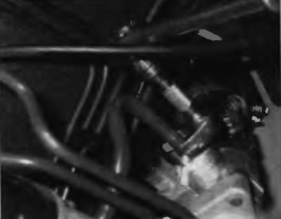
Pic. 20.2b. Disconnect the power steering line fitting using the special wrench fit (designed for choke connections) and a short extension
3. Mark position of an intermediate shaft concerning the universal joint of a steering shaft and turn out a coupling bolt. Loosen the clamping bolt of the shaft cover and remove the cover towards the top (pic. 20.3).
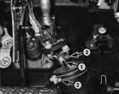
Pic. 20.3. Elements of the upper intermediate shaft
1 - Mark the position of the upper intermediate shaft relative to the universal joint of the steering shaft
2 - Clamping bolt of the shaft cover
3 — Coupling bolt of the cardan hinge of a steering shaft
4. On models equipped with electronically controlled air suspension, disconnect the ride height sensor linkage from the left transverse arm, then remove the sensor.
5. Mark the position of the lower countershaft universal joint relative to the steering input shaft, and then remove the universal joint pinch bolt (pic. 20.2,a).
6. Separate the tie rod ends from the steering knuckle arms (see paragraph 18).
7. Disconnect the stabilizer struts from the ends of the stabilizer and unscrew the bolts securing the bushing clamps (see paragraph 2).
Application. The steering gear mounting bolts cannot be removed until the stabilizer bar is moved to the side.
8. Turn away nuts of fastening of the steering mechanism (pic. 20.8), raise the stabilizer and knock out the steering gear mounting bolts.
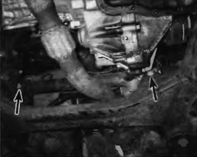
Pic. 20.8. Steering gear nuts
9. Separate the universal joint of the intermediate shaft from the input shaft of the steering gear and remove the steering gear assembly through the left side of the vehicle.
10. Check steering gear mounting bushings for excessive wear or deterioration. Replace them if necessary.
Installation
11. Raise the steering mechanism to the installation height and connect the universal joint of the intermediate shaft to the input shaft of the steering mechanism, aligning the alignment marks.