



- a) Make sure that the wire clamps on the battery terminals are clean and securely fastened.
- b) Check the condition of the battery wires (see paragraph 4). Replace all faulty battery cables with new ones.
- c) Check the battery status (see paragraph 3). If it does not pass all the tests, replace it
- d) Check the wiring and connections of the starter solenoid. Refer to "Electrical circuits" at the end of chapter 12.
- d) Check the tightness of the starter mounting bolts.
- e) Check the fuse link (see chapter 12). If it is burnt out, find out the reason and repair the electrical circuit.
- g) Check the operation of the park/neutral switch sensor. Make sure the gearshift lever is in the P or N position. For information on checking and adjusting the park/neutral switch sensor, refer to chapter 7. When performing electrical circuit checks, refer to the following if necessary: "Electrical circuits" in Chapter 12, all three systems must be functioning properly to ensure that battery voltage is supplied to the starter solenoid.
- h) Check the operation of the starter relay. The starter relay is located in the fuse/relay box in the engine compartment. For a description of the relay test procedure, refer to chapter 12.
2. If the starter does not engage when the ignition switch is turned to the start position, check for battery voltage to the solenoid. This will show whether the solenoid is receiving the correct voltage signal from the ignition switch. Connect a test light or voltmeter to the positive terminal of the starter solenoid and read the voltage while an assistant turns the ignition switch to the start position. If there is no voltage, contact "Electrical circuits" in Chapter 12 and check all fuses and relays in series with the starting system. If voltage is present but the starter does not operate, remove the starter (see paragraph 13) and check it on the stand (see point 4).
3. If the starter turns slowly, check the starter cranking voltage and battery amperage. This test should be performed with the starter on the engine. Crank the engine for no more than 10 seconds and observe the battery voltage. It should not fall below 8.0 volts on manual transmission models or 8.5 volts on automatic transmission models. Also observe the amperage on the ammeter (Fig. 12.3). It should not exceed 400 amps or fall below 250 amps. If the starter cranking amperage is not within the specified range, replace the starter with a new one. There are several factors that can affect the ability of the starter to crank. The battery should be in good condition and the battery cold cranking amps should not be lower than the specification for the specific application. Check the battery specifications carefully. The battery terminals and cables should be clean and free of corrosion. Also, if the temperature is too low, warm up the battery and/or cylinder block before performing checks.
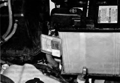
Fig. 12.3 To use an inductive ammeter, simply hold the ammeter over the positive or negative wire, whichever is easier to access
4. If the starter receives voltage but does not activate, remove it and test the starter assembly with the solenoid on a stand (Fig. 12.4). Most likely, the solenoid is faulty. In some rare cases, the engine may seize. Therefore, before continuing, try to turn the crankshaft pulley (see chapter 2A or 2B). Having secured the starter assembly with the electromagnet in a vice on the stand, pull one connecting wire from the negative terminal of the battery to the starter housing. Pull the other connecting wire from the positive terminal of the battery to the B+ terminal on the starter. Set the start switch, apply battery voltage to the S terminal of the electromagnet (10 seconds or less) and see if the solenoid plunger, shift lever, and overrunning clutch extend and if the pinion gear rotates. If the pinion gear extends but does not rotate, the solenoid is working but the starter is faulty. If there is no movement but the solenoid clicks, the solenoid and/or starter are faulty. If the solenoid plunger extends and the pinion gear rotates, the starter/solenoid assembly is working properly.
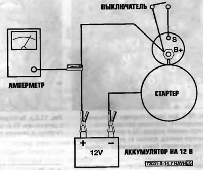
Fig. 12.4. Starter funnel on the stand
The text is quoted from the source website Toyotaman.ru