
2. System elements include a powertrain control module (PCM), VVT oil control valve (OCV) and intake camshaft sprocket/actuator (pic. 5.2 a, b).
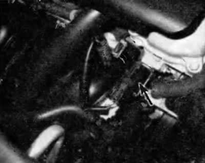
Pic. 5.2, a. variable valve timing oil control valve (DOP is located on the right end of the cylinder head (on the passenger side)
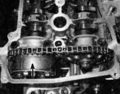
Pic. 5.2b. The inlet fork actuator is only visible when the cylinder head cover is removed
3. The PCM uses input from the following sensors to turn the oil control valve on and off:
- A) vehicle speed sensor (VSS),
- b) throttle position sensor (TPS),
- V) mass air flow sensor (MAF),
- G) engine coolant temperature sensor (EATING).
4. When the VVT oil control valve is activated by the PCM, it directs the prescribed oil pressure from the engine to advance or retard the intake camshaft sprocket/actuator.
5. The intake camshaft sprocket/actuator has an internal hub that is fixed to the camshaft. The inner hub contains a set of fixed vanes that are subjected to oil pressure to turn the camshaft. The higher the oil pressure (or expense), the faster the actuator will rotate, causing the camshaft to advance or lag.
6. When oil is supplied to the vanes from the advanced side, the actuator can advance the camshaft by up to 21°clockwise. When oil is supplied to the vanes from the lag side, the actuator begins to turn the camshaft counterclockwise to 0 degrees, which corresponds to the normal position of the actuator when the engine is running at no load or at idle. In addition, the PCM can send a signal to the oil control valve to stop the oil supply to both channels (advances and delays), to maintain the camshaft advance in the current position.
7. Under light engine load, the VVT system will initiate camshaft retardation to reduce valve overlap and stabilize engine power. At moderate engine loads, the VVT system will advance the camshaft to increase valve overlap, while reducing fuel consumption and emissions. Under heavy engine loads at low revs, the VVT system advances the camshaft to allow the intake valves to close more quickly, which improves low and mid-range torque. Under heavy engine loads in the high rpm range, the VVT system initiates camshaft retardation to slow the closing of the intake valves to increase engine power.
Replacing elements
Application. Problems in the electrical circuit of the WT oil control valve cause a diagnostic trouble code to be generated and a warning lamp on the instrument panel to turn on «CHECK ENGINE» (check engine). See Chapter B for information on fault codes.
Note. Most problems in the VVT system are caused by the oil control valve and the associated filter. This valve requires regular engine oil and filter changes to keep it running smoothly.
Oil Pilot Filter
8. Blockage of the strainer of the control oil valve (OCV) very often causes problems in the operation of the VVT system. Remove the OCV filter from the rear of the cylinder head and then inspect it for blockage. If necessary, clean the filter and reinstall it using a new O-ring. The larger end of the filter must face the head
Control oil valve
9. To replace the oil control valve (OCV) unscrew the retaining bolt and remove the valve from the cylinder head. The valve is located on the front side of the cylinder head (near the timing chain). When installing a new valve, use a new O-ring. Tighten the valve bolt to the specified torque specified in Specifications at the beginning of this chapter.
Sprocket/Camshaft Actuator
10. Remove the cylinder head cover (see paragraph 4), timing chain (see paragraph 6) and intake camshaft (see paragraph 7).
11. Clamp the camshaft in a vise on a workbench. To clamp the shaft follows the hex section of the shaft.
Warning. Be careful not to damage the camshaft, its balls and necks.
12. Make sure that the sprocket/actuator does not rotate from the fixed position. The detent position is the neutral position that the actuator assumes when the engine is running at idle and no load, and at any time when the VVT system is not activated by the PCM.
13. Using a brake cleaner, remove all traces of oil from the front washers and from the VVT control oil ports. Apply vinyl tape to all control holes except for the oil port on the advance side.
14. Apply air pressure 1.5kg/cm2 into the oil port on the advance side and try to turn the actuator by hand. The actuator must rotate freely, without obvious jamming in the direction of increasing the lead from a fixed position.
Note. A tight seal is required between the air gun tip and the advance oil port hole because if there is an air leak at the air gun tip or any other control oil port, the locking pin in the actuator will not come out of the locating hole. If a leak occurs, apply slightly more air pressure to the advance side oil port to force the lock pin out of the mounting hole.
15. If the actuator does not rotate as freely as prescribed, replace the intake camshaft sprocket/actuator.
16. To replace the sprocket/actuator, clamp the camshaft in a vise on the imposition and unscrew the nut.
Warning. Do not unscrew the four bolts from the VVT actuator.
17. Remove sprocket/actuator. If the element cannot be removed from the camshaft, lightly tap it with a plastic-faced hammer.
Warning. Do not attempt to disassemble the sprocket/actuator. This is a non-separable unit, it is impossible to assemble it again.
18. Lubricate the bearing surface for the sprocket/actuator on the camshaft with clean engine oil. Install the sprocket/actuator onto the shaft so that the groove is aligned with the pin. When the pin is fully seated in the groove, turn the sprocket/actuator further to the right (side of delay). Install the sprocket/actuator mounting nut and tighten to the specified torque as specified in Specifications at the beginning of this chapter.
Note. Make sure that the sprocket/actuator can move on the retard side and locks in the limit position on the retard side.
19. Install the intake camshaft (see paragraph 7), timing chain (see paragraph 6) and cylinder head cover (see paragraph 4).